Photonics HandbookFeatures
Advanced Manufacturing Unlocks the Full Potential of Aspheric Optics
A range of fabrication methods is making aspheres accessible for applications ranging from smartphone cameras to space telescopes and beyond.
By Anna Wang and Robert Bourdelais
Aspheric lenses and mirrors can enhance the performance of optical systems while reducing their size and weight. Spherical optical surfaces often fail to form an ideal image or bring a laser beam to its best possible focus — a fundamental limitation that arises from the way that spherical surfaces interact with light. High-performance optical systems typically rely on the use of multiple spherical elements to compensate for this property.
By definition, aspheric optics bypass this design strain. Their geometry inherently offers better optical system performance and enables designers to build with fewer elements.

Courtesy of iStock.com/ALIOUI Mohammed Elamine.
However, the difficulty in fabricating aspheric surfaces historically confined their use to a handful of specialized applications.
This has changed in recent decades as
a result of the development of several
advanced asphere manufacturing techniques. Each of these methods offers benefits, as well as trade-offs that are determined by factors including (but not restricted to) accuracy, speed, and cost.
A manufacturing challenge
The reason asphere fabrication has historically been characterized by complex processes is rooted in the shape of these optics. A sphere is rotationally symmetric about all axes and lacks a vertex. If two nearly spherical surfaces — one convex and one concave — are placed in contact and moved randomly against one another under uniform pressure, they tend to wear into closely matched, highly spherical shapes. This self-correcting property is the basis of traditional optical polishing. It enables the fabrication of remarkably precise spherical surfaces with relative ease.
In contrast, self-correcting polishing processes do not naturally produce aspheres or freeform surfaces. Aspheres, though often rotationally symmetric, still have a defined axis and vertex. Freeform optics are more complex still; these optics lack both axial symmetry and a well-defined vertex. Fabricating these surfaces requires controlled, deterministic processes tailored to the specific geometry of the optic.

Aspheric lenses already play key roles in aerospace and defense systems, satellite imaging, laser cutting and welding, and more. Advancements in manufacturing techniques, metrology, and alignment/assembly promise to expand their use further. Courtesy of MKS.
This requirement, though well understood, poses a substantial challenge to manufacturing.
Single-point diamond turning
Single-point diamond turning (SPDT) is a widely used method to generate both rotationally symmetric and freeform optical surfaces. It is largely analogous to the traditional machining of metal parts on a lathe. However, in SPDT, the tool bits are natural or synthetic diamonds that have been precision-lapped to ultrahigh accuracy (<0.15 µm) and mounted on steel or carbide shanks.
The SPDT lathe is a much more sophisticated and accurate machine than a traditional metal lathe. It is equipped with an air bearing spindle and driven by a linear motor. These hydrostatic aspects of design limit mechanical noise from being transferred onto the surface of the part.
Optical designers routinely use SPDT to fabricate optics with surface accuracies in the λ/4 to λ/8 range (at 632.8 nm). This value is comparable to that which designers achieve using traditional optical polishing methods. However, SPDT usually delivers a surface roughness in the 1- to 5-nm range — a value range that is inferior to the subnanometer roughness value range achieved via traditional polishing. As a result, SPDT is used mostly for infrared optics, as the higher levels of surface roughness have minimal effect on longer wavelengths. Additionally, because each part is fabricated individually in SPDT, the technology is generally unsuitable for extremely high-volume production.
Still, SPDT remains a common production method for most of the low-to-medium-volume, high-precision infrared optics used in imaging and laser applications. Iterative gains in supporting
technology have also benefited SPDT: The introduction of slow-tool servo and xzc turning techniques, for example, represents one of the most important advancements that has occurred in SPDT during the past 30 years. These techniques enable the precise coordination
of the tool’s linear (x and z) motions with the part’s rotary (x-axis) motion, allowing the diamond tool to follow complex,
nonrotationally symmetric paths. This in turn makes it possible to machine advanced freeform surfaces and off-axis parabolas and ellipses in a single operation, without the need to reposition the part or change tooling.
Magnetorheological finishing
Magnetorheological finishing (MRF) is an advanced, deterministic polishing technique for fabricating aspheres. To perform MRF, a single optic is held on a spindle and rotated.
Instead of using a diamond tool or traditional polishing lap, MRF uses a magnetorheological fluid to shape the component. This fluid consists of magnetic particles in a carrier liquid. Placing the fluid in a magnetic field changes its viscosity, and it becomes more solid-like. Both the fluid shape and viscosity are controlled in real time using magnetic fields to dynamically shape the polishing tool.
MRF offers several advantages compared with traditional polishing methods: It can be used to achieve extremely smooth surfaces with low roughness and correct surface errors at the nanometer scale using a 3D metrology input map to create a dwell-based polishing tool path. The approach is widely used to produce high-quality aspheric lenses for astronomy, microscopy, and other applications.
To produce aspheres with a surface
figure <λ/100 (PV), MRF can be combined with a precise, repeatable interferometer setup. For example, MKS uses a combined MRF/aspheric stitching interferometry technology to fabricate high-departure, steep aspheres without the need for custom tooling. The interferometric method enables the fabrication
of λ/20-accuracy aspheres, including control of low-order Zernike polynomial requirements to further mitigate assembly-level errors. The use of various wheel sizes and machine parameter adjustments enables the MRF spot to be morphed so that the desired spatial frequencies can be deterministically targeted and corrected.
Precision molding
For more than 50 years, optical developers have applied precision molding to produce medium-quality aspheres at high volumes. Molding starts with the creation of a tool that contains a cavity in the shape of the finished aspheric optic. This mold can also incorporate mounting flanges, holes, and/or other mechanical features directly into the optic.
Glass and polymer optics are usually molded using different processes. In precision glass molding, for example, a preformed glass blank is heated to near its softening point and pressed into the mold. Then, it is carefully cooled to retain the desired shape. For plastics, molten material is injected into a mold cavity, where it solidifies into the final optic.
Molding is a highly efficient means for producing large quantities of lenses with consistent quality and low unit cost. Precision molding is commonly used for lenses in consumer electronics, such as smartphones, for which high volume and uniformity is an essential combination.
Computer-controlled polishing
In traditional optical fabrication, a polishing tool that is the diameter of the component or larger is repeatedly passed over the component surface. Successively finer abrasives bring the optical surface from a rough ground to a highly polished state. As mentioned, the use of a spherical polishing tool in this manner will naturally produce a spherical optic.
Computer-controlled polishing (CCP) modifies this method to enable production of aspheres and freeforms. Typically, it relies on subaperture polishing, in which a polishing tool that is much smaller than the optical surface is moved over the part surface in a precise, computer-controlled pattern. The computer ensures the continual adjustment of tool pressure, speed, and dwell time at each location, reaching values of each parameter that are optimal to remove material as needed and yield the desired nonspherical shape.
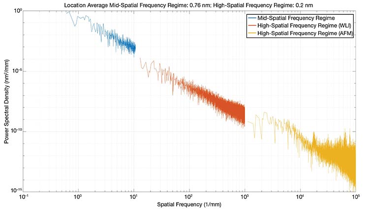
This power spectral density (PSD) plot combines three sets of measurements into an integrated data set analyzing the part under test. The graph shows the part’s surface characteristics across four orders of magnitude in spatial sampling, from microroughness to surface figure. Courtesy of MKS.
Subaperture polishing offers exceptional control over the optical figure. But it can also introduce a new challenge: mid-spatial frequency (MSF) errors. These are periodic or quasiperiodic surface features of a size and periodicity that fall between traditional low-frequency (figure) and high-frequency (surface roughness) optical surface errors.
MSF errors are particularly problematic in systems where stray light, diffraction, and/or laser beam quality are critical
since these errors can scatter light in unintended ways. Advanced polishing processes must therefore achieve the desired surface figure and actively manage and mitigate MSF errors to meet stringent optical performance requirements.
Each manufacturer uses its own tooling and algorithms to achieve this goal, and MKS developed its own embodiment of the technology that can be adapted to target specific, often extreme, requirements that otherwise would not be efficiently achievable. For example, the MKS CCP method aims to bring versatility in adapting processes specific to any glass, ceramic, metal, or crystal that may otherwise be problematic. Specifically, with these materials, parameters can be engineered to target extremely low roughness values or mitigate problematic MSF errors that often arise with other techniques.
Precision replication
As is true of precision molding, methods for optics production using replication have been available for many decades. Designers often struggle to use these methods to deliver precision surfaces, though, and in many cases, they have historically required additional tooling, which carries additional design expense that must be absorbed.
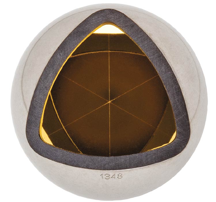
Replicated hollow metal retroreflectors from MKS/Newport are monolithic and typically fabricated from a single piece of aluminum, resulting in return beam
accuracy that is unaffected by vibration or angle. The retroreflector shown is used in laser tracking. Courtesy of MKS.
A recent process innovation in replicated optics aims to enable the integration of optical and mechanical features into a single part. The process begins with the fabrication of a high-precision master, which is typically generated using five-axis diamond turning and then further refined via advanced metrology and polishing. Once the master achieves the required surface accuracy and roughness, often in the range of λ/10 to λ/20, a release layer and reflective coating are applied. Substrates are then prepared for the replicas. These can be made from a wide range of materials, including metals, glass, ceramics, and composites.
Crucially, these substrates do not require precision optical surfaces: The replication process erases existing surface errors, transferring the surface quality of the master onto the replica. During replication, the master and substrate are bonded together using a thin adhesive layer. Once the adhesive cures, the master is removed, leaving behind an accurate, high-quality optical surface on the replica. The master remains unchanged and can be reused many times.
This technique offers high integrability, excellent thermal stability, and enhanced production efficiency. It also supports volume asphere and freeform production at low cost. It is deployed across fields from aerospace and medical instrumentation to lidar and consumer electronics.
Ion beam figuring
Ion beam figuring (IBF) is not a primary shaping method. Rather, it is a process used as a final corrective step to improve a surface created using another fabrication method such as SPDT, MRF, and/or CCP.
In IBF, an ion beam generator emits particles that are electrostatically accelerated and then collide with the optical surface. The ion impact removes just a few atoms of material in a highly controlled manner.
A user can input a 3D metrology map to create a dwell-based ion beam path and use this approach to achieve low surface figure and slope error on aspheres and freeforms. Multiple configurations of grid sets and beam apertures can be used to correct a large variety of features in the low-spatial-frequency range. IBF is especially useful in targeting very tight surface figure specifications while minimizing the degradation of surface roughness and edge roll-off effects.
Ultralow expansion glass
The precision optics industry has adopted SPDT, MRF, CCP, and IBF for a range of optics types and optical materials. Yet some optical materials merit individual treatment and command tailored fabrication and processing techniques. Ultralow expansion (ULE) glass — for example, for use in stepper optics, mirror blanks, and photomask substrates — and Zerodur, which is used commonly in space and telescope optics, are examples of such materials. The precision optics and aerospace and defense applications in which these materials are widely used are such that even minimal deformation can negatively influence performance. At the same time, their brittle nature and strict dimensional stability requirements pose substantial manufacturing challenges.
The steps to process these materials vary by manufacturer. But regardless of the approach, real-time metrology, vibration isolation, and temperature stability are critical during processing to prevent microfractures and dimensional drift.
Asphere and Freeform Fabrication Technologies: An Overview

Courtesy of MKS.
At MKS, following machining, hydrofluoric acid etching is deployed to remove subsurface damage and residual stress. The etching process is carefully tuned for each material; ULE, with its homogeneous structure, etches more uniformly than the heterogeneous Zerodur. To protect polished or critical surfaces during this etching process, a masking technique is applied to ensure only targeted regions are exposed to the acid. Metrology-guided process control functions balance mechanical machining with chemical etching, ensuring precise dimensional outcomes. This integrated approach also supports complex, high-aspect-ratio features while maintaining optical quality.
In addition to achieving tight dimensional tolerances, the machining and etching processes accommodate complex geometries, including features with high-aspect ratios such as deep, narrow channels with <3-µm perpendicularity, 1-µm flatness, and 20-µm true position over a length of 400 mm. These features present additional challenges due to the increased risk of microfractures and difficulty
in accessing tight spaces for chemical
etching.
Nevertheless, an integrated approach can be implemented to ensure that such complex and high-aspect-ratio features are produced reliably without compromising the structural integrity or optical quality of ULE and Zerodur components. MKS’ method combines precise CNC tool paths with controlled acid-etching and real-time metrology.
Metrology and assembly
Metrology is integrated throughout the production process in the fabrication of aspheres and freeforms. The first step in most deterministic manufacturing processes is to generate a sag table or surface map registered to the part’s physical datums. This enables meaningful feedback between metrology and each fabrication cycle. Parts with large departures from a sphere or tight registration requirements pose special challenges. A combination of techniques, including aspheric stitching interferometry, as well as computer-generated holograms and stylus-based probes can be used to obtain accurate measurements of a surface figure. Attaining accurate registration between the metrology data and the physical part is essential in this context, particularly for off-axis designs sensitive to decenter or tilt.
One approach to ensure consistency is to mount both test parts and reference optics on hexapods or three-axis motorized stages. These can then be integrated with coordinate measuring machines to simultaneously capture datum, focus, and wavefront data, ensuring reproducible part registration and convergence between finishing cycles.
Surface roughness and MSF errors are critical performance parameters in many applications. This is evidenced by customers who often specify spatial sampling across a wide range of scales, from nanometers to millimeters. Providing a complete surface characterization is paramount, and MKS combines data from multiple instruments to generate stitched power spectral density (PSD) plots.
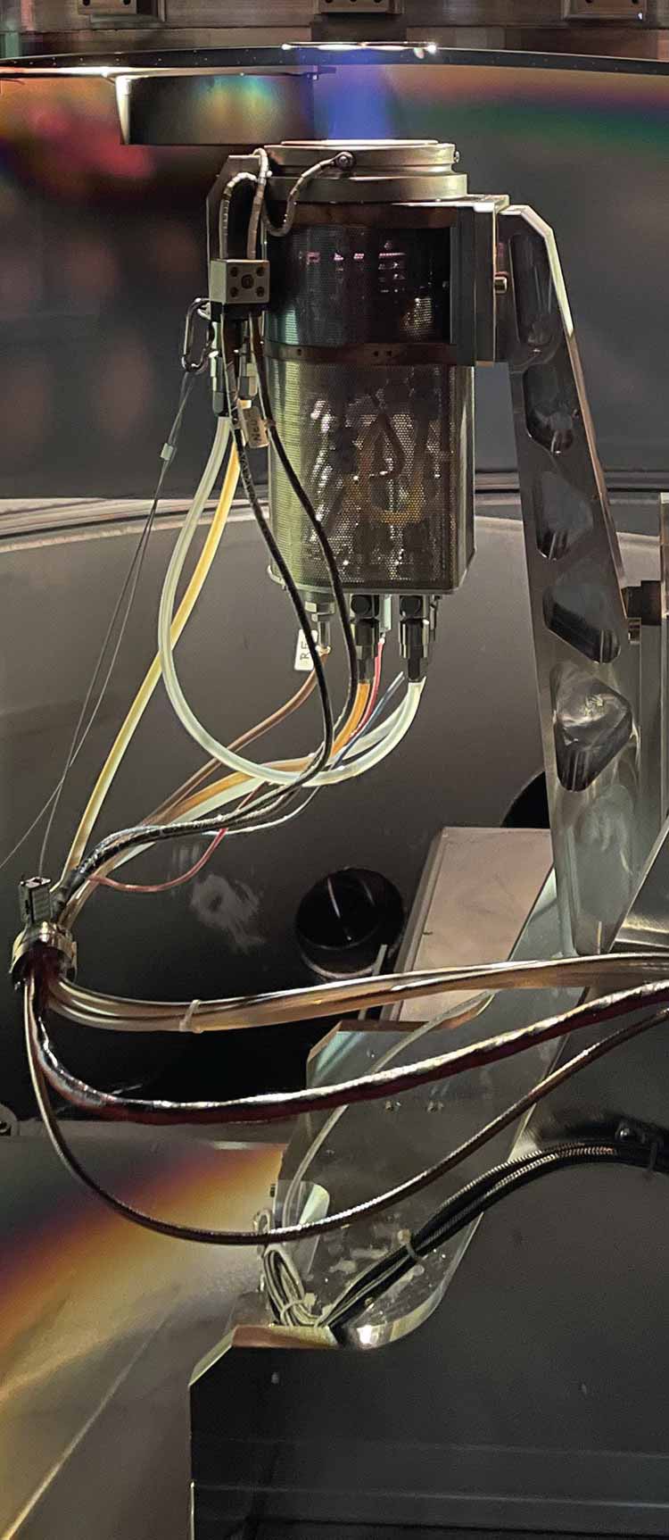
Ion beam figuring (IBF) is used to deterministically correct a large metal mirror.
Courtesy of MKS.
Also, verifying surface accuracy
becomes even more important as system tolerances continue to tighten. Surface errors are typically categorized into form errors, waviness, and surface roughness. Other performance metrics include focal length, image quality, and system aberrations.
Interferometry today is still the primary method for measuring surface accuracy at the nanometer level. Profilometry is a complementary technology, capturing surface roughness and waviness through direct scanning. In combination, these tools ensure comprehensive verification of aspheric and freeform optical surfaces.
Metrology also has a direct throughline to assembly; to preserve the performance level achieved with high-accuracy surfaces, precision must be maintained all the way through the assembly process.
Datum-structured alignment is one way to ensure the precise positioning of aspheric lenses during manufacturing and assembly. It involves the use of reference points or surfaces (datums) on the lens or its holder to align the lens accurately.
Alignment turning is another technique. It can be performed after the aspheric lenses have been mounted in their holders and involves rotating the lens holder while monitoring the optical performance, adjusting as needed to achieve optimal alignment.
Aspheres and the future of optics
The distinct properties of aspheric optics have made them indispensable in diverse applications. While too numerous to list exhaustively, a quick survey of current applications provides a sense of how widely they are used today. Precision aspheres are now found in cameras, microscopes, telescopes, AR/VR headsets, ophthalmic instruments, and automotive head-up displays. They also play key roles in aerospace and defense systems, satellite imaging, laser cutting and welding, endoscopy, spectroscopy, optical interferometry, and machine vision.
Ongoing advancements in aspheric manufacturing techniques, metrology, and alignment/assembly promise to expand their use even further.
“Optics, developing in us through study, teach us to see.” This quote, attributed to Paul Cézanne, reflects how the study of optics deepens both our technical understanding and our perception of the world. Aspheric optics exemplify this: They enable sharper images, more precise measurements, and new ways of exploring what has been and what is to come.
Meet the authors
Anna Sansan Wang is a senior product manager at MKS/Newport. She has held a variety of leadership roles spanning sales, marketing, web development, product development, and operations. Wang has a Bachelor of Science
degree in optical engineering from the
University of Rochester; email: anna.wang@mks.com.
Robert Bourdelais is senior global business manager for MKS/Newport. He has more than 30 years of industry experience, including in engineering, R&D, operations management, and product management. He is the author of more than 200 issued patents; email: robert.bourdelais@mks.com.
/Buyers-Guide/MKS-Newport/c10219
Published: September 2025
Glossary
- magnetorheological finishing
- Magnetorheological finishing (MRF) is a precision optics polishing technique used for shaping and finishing optical surfaces to achieve extremely high levels of smoothness and accuracy. It is commonly applied to lenses, mirrors, prisms, and other optical components in various industries, including astronomy, microscopy, and laser systems.
The process involves using a magnetorheological fluid—a liquid containing ferrous (iron) particles—and a magnetic field to perform the...
- diamond turning
- Diamond turning, also known as diamond machining or diamond cutting, is a precision machining process used to produce high-quality optical surfaces and components with extremely tight tolerances. It involves the use of a single-point diamond cutting tool to remove material from a workpiece, typically made of metals, plastics, or optical materials like glass or crystals.
In diamond turning, the cutting tool, which has a diamond tip, is controlled with high precision and moved relative to the...
- polishing
- The optical process, following grinding, that puts a highly finished, smooth and apparently amorphous surface on a lens or a mirror.
- glass
- A noncrystalline, inorganic mixture of various metallic oxides fused by heating with glassifiers such as silica, or boric or phosphoric oxides. Common window or bottle glass is a mixture of soda, lime and sand, melted and cast, rolled or blown to shape. Most glasses are transparent in the visible spectrum and up to about 2.5 µm in the infrared, but some are opaque such as natural obsidian; these are, nevertheless, useful as mirror blanks. Traces of some elements such as cobalt, copper and...
- optical assembly
- An optical assembly refers to a collection of optical components that are carefully arranged and aligned to perform a specific function within an optical system. These components may include lenses, mirrors, prisms, filters, fibers, detectors, and other optical elements. The purpose of an optical assembly is to manipulate, control, or analyze light in various ways to achieve desired optical outcomes, such as focusing, collimating, dispersing, filtering, or detecting light.
optical assembly...
aspheric lensesOpticsMKSMKS NewportaspheresRobert Bourdelaisprecision opticsfinishingMagnetorheological FinishingMRFdiamond turninglensesFeaturesmoldingpolishingion beam figuringglassoptical metrologytest and measurementoptical assemblyAnna Wang