Thirty-five years after the introduction of cross-correlation for particle image velocimetry, a technique that relies on AI could change the way flows are measured.
WOJCIECH MAJEWSKI, MICROVEC PTE. LTD.
The first article to use the term “particle image velocimetry” (PIV) was published in 1984. Since then, PIV has become a standard method for flow measurements. The technique has remained largely unchanged over the past 35 years. Continuous lasers or special double-pulse lasers, also known as PIV lasers, are used to generate laser light sheets with special optics. The light sheet illuminates a plane that makes visible the seeding particles that follow the flow. The light scatters off the particles and an image is taken with a camera, capturing an instantaneous snapshot of the flow (Figure 1). By taking a second image shortly afterward, the displacement of the particles between these two images can be seen. Then, by applying a cross-correlation algorithm, the velocity vectors can be calculated to find the direction and speed of the flow. When the analysis for the entire image has been completed, the resulting velocity field, vorticity field, and many other flow characteristics can be
visualized and analyzed.
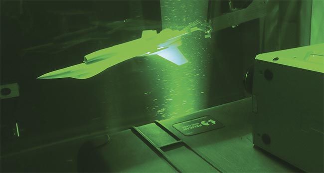
Figure 1. A typical PIV application showing a study of the flow behind the tail section of an airplane model. Courtesy of Microvec Pte. Ltd.
Lasers are key components in PIV
measurements because they provide high-intensity coherent illumination. Various
lasers have been developed specifically to help PIV get better results. The most common lasers used are Nd:YAG
(neodymium-doped yttrium aluminum garnet) (532 nm) with dual oscillators that are capable of generating two pulses with very short time intervals, down to nanoseconds. They have energy levels ranging from
50 to 500 mJ. The higher the energy level, the more planar area or volume the laser can illuminate, giving researchers the ability to measure large flows.
Another common type of PIV laser is the Nd:YLF (neodymium-doped yttrium lithium fluoride) (527 nm), used mainly with high frequencies and time-resolved measurements that generate pulse frequencies up to 10 kHz. These wavelengths correspond to the highest quantum efficiency of the CCD or CMOS sensors used in digital cameras.
Until recently, PIV used a traditional method of capturing an image pair that showed the particles scattering light, and then used cross-correlation algorithms to analyze the particle displacements based on the two images. This math is commonly performed on a grid with interrogation windows sized 64 × 64, 32 × 32,
or 16 × 16 pixels in 2D PIV cases, to calculate the mean velocity vector for the particles within the windows. The smaller the size of the window, the higher the resolution of the flow result (Figure 2). However, a too-small window will contain fewer particles, which leads to difficulty in matching particle pairs and increases the measurement uncertainty. This becomes an obvious spatial resolution limitation in traditional PIV measurement techniques. Any information associated with small-scale flow structures remains undetected.
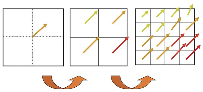
Figure 2. Velocity vector fields with interrogation regions of 64 × 64, 32 × 32, and 16 × 16 pixels. Courtesy of Microvec Pte. Ltd.
The traditional way to determine or predict the flow of information between particles is to perform the interpolation using mathematical approaches, because this method can get more velocity vectors. Unfortunately, the interpolated vectors are normally unphysical, meaning they fail to satisfy the governing equations of flows and do not represent the physical mechanism of flows. The new artificial intelligence (AI) PIV technique, however, which uses deep learning and convolutional neural networks, promises to end this limitation by generating velocity vector fields with a resolution down to a maximum of
1 pixel. This significantly improves the spatial resolution and could become a disruptive technique that changes the way flows are measured in fluid mechanics research. With the use of deep learning, AI PIV has the capability to achieve superresolution of image processing. The technique will be able to predict undetermined flows of a small scale by learning physical mechanics through training procedures from a large data set of flows that restrictively satisfy the governing equations of fluid mechanics (Figure 3).
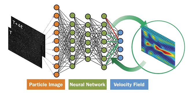
Figure 3. The principle of a deep neural network for PIV. Courtesy of Microvec Pte. Ltd.
The underlying idea is to design a deep learning estimator for fluid motion. A convolutional neural network such as this works as a mapping function from images to motion. Its input is the same as in traditional PIV — for example, using two consecutive images to get a velocity field output. The result is a deep neural network (DNN) for PIV, which can provide velocity fields with up to one vector for a single pixel in an accurate and efficient way.
The design principle is based on the optical flow computation, which is then combined with deep learning processes to create a deep learning motion estimator. Optical flow computation relies on the optimization of an objective function and provides a dense motion field for the whole image as opposed to the sparse motion field obtained by traditional PIV. Optical flow computations by themselves are generally time-consuming and sensitive to noise; therefore, it becomes a challenge to obtain precise results with real-life PIV images.
To accurately map the images to a corresponding motion in accordance with the laws governing fluid mechanics, the ground truth fluid motions are simulated by solving governing equations using computational fluid dynamics (CFD). The
data set of synthetic particle images based on these flow motions is generated as training data. This information is then used to train the networks.
Since the results of the generated outcomes are reliable and accurate based on the solving of governing equations, synthetic images are used to generate data sets. Every single data item contains an image pair (input) and a true velocity field (output) (Figure 4). In Steps 1 and 2, a particle image and a flow motion pattern is generated. In Step 3, the positions of the particles are shifted symmetrically by the flow motion to generate an image pair and to find the true theoretical result.

Figure 4. The principle of generating a data set for training of the deep neural network. Courtesy of Microvec Pte. Ltd.
There are general rules to follow when producing these synthetic particle images. Each particle can be described by a 2D Gaussian function. The parameters that determine an image include the distribution of particles, along with the diameter, seeding density, and peak intensity. These factors are randomly selected in a suitable range to build a unique particle image that imitates real-life PIV images. To ensure the largest possible diversity of the training data set, various flow patterns are used. These include laminar and turbulent flows at various speeds. Typical flows include: flows around cylinders, spheres, and other objects; backward stepping flows; jet flows; wake flows; wall-bounded turbulence; and homogeneous isotropic turbulence. Tens of thousands of image pair combinations with accurate results currently exist. More combinations will be added over time to make the results more precise and reliable.
To make the data set more accurate, various types of imaging noises are added in the training particle images to simulate the real experimental conditions associated with laser illumination. Special conditions of PIV imaging are also considered, including the out-of-plane issue, the laser reflection off the wall, and the moving boundary-of-flow field.
DNN-trained AI PIV software used on artificial data was successfully applied to real experiments and their respective images. An example shows measurement results of a jet flow, which can form typical flow types and structures common in fluid mechanics, such as high-speed flow regions, shear flows with strong velocity gradient, and complex vortices with scales of various lengths. Traditional PIV software based on cross-correlation algorithms has been used to calculate results with a grid of 32 × 32 pixels (Figure 5), and AI PIV software has been used to calculate the results (Figure 6) without the grid limitation. The dark areas in the images are formed by all the vectors displayed in the image. Both results are similar on the large scale; however, since the dense velocity field obtained in AI PIV contains more detailed information down to the single-pixel level, the results are smoother and show a new level of detail. An unresolved small vortex structure can be detected (Figure 8). It was previously invisible in Figure 7 because of the spatial resolution limitations of the
traditional PIV software. Accuracy of both
velocity and velocity gradient is significantly improved, which would benefit the
study of turbulent flows on the energy spectrum.
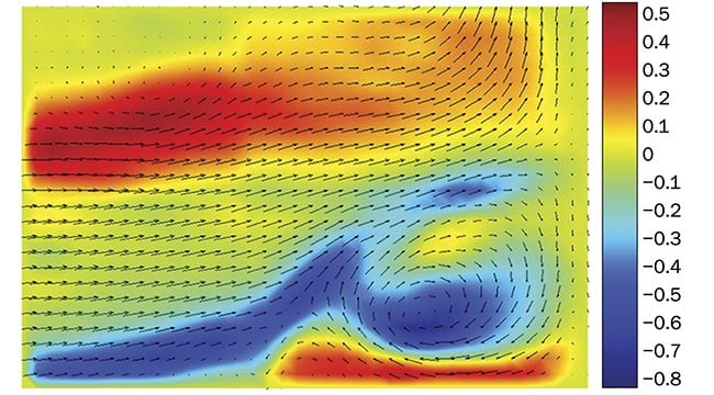
Figure 5. A cross-correlation PIV result. Courtesy of Microvec Pte. Ltd.
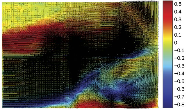
Figure 6. An AI PIV result. Courtesy of Microvec Pte. Ltd.
This is just the beginning. The adoption of AI in fluid mechanics will continue to evolve and improve. Thousands more images will be added to the training data set to make this AI solution more accurate and even more capable of obtaining results from experimental flows. Beyond the technological breakthrough, real-life applications in academic research and industrial design of the products handling these flows will open new possibilities — from the aviation field designing more aerodynamic aircrafts, and the mechanical and civil engineering fields achieving efficient and energy-saving water flow and drag reduction in oil pipelines, to the medical field and hemodynamics assessing blood flow to detect early signs of heart attacks. The ability to better understand flows with an unprecedented resolution and more accuracy has the potential to transform the field of fluid dynamics.
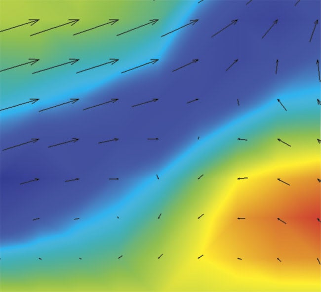
Figure 7. A detailed cross-correlation PIV result. Courtesy of Microvec Pte. Ltd.
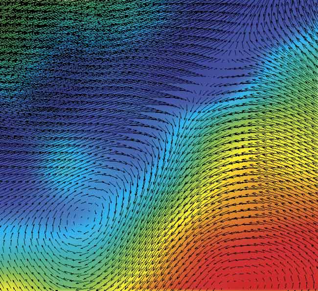
Figure 8. A detailed AI PIV result. Courtesy of Microvec Pte. Ltd.
Meet the author
Wojciech Majewski is a managing director of Microvec Pte. Ltd., a Singapore-based company that offers innovative fluid mechanics systems.