Imaging via multiphoton microscopy is challenging at deeper levels, especially in the study of delicate structures. Automated spherical aberration correction systems are addressing the problem.
CARLO ALONZO, OLYMPUS CORP. OF THE AMERICAS
Multiphoton microscopy is widely regarded as the primary technique for deep imaging in live tissue. However, image brightness and resolution are typically poorer at deep sites because of increased optical spherical aberration compared to superficial locations. This makes it difficult to study fine structures, such as dendritic spines in deep brain regions.

Microscope objectives equipped with adjustable correction collars can compensate for spherical aberration and improve resolution by moving internal lens elements. Motorized correction collars facilitate more precise and convenient operation compared to direct manual control. Often, however, corrections are only applied at a static depth within the specimen.
An automated correction collar that dynamically adjusts with focus depth represents the next advancement in deep imaging. By tailoring optical corrections to depth and refractive index profile, brighter images and finer features can be captured from deeper inside biological tissue.
Recent and ongoing advancements in many fields of the biological sciences are founded on a better understanding of dynamic interactions between cells and their surrounding microenvironment. Insight into complex biological processes, such as wound healing in skin or memory formation in the brain, requires more than just static measurement of structural and biochemical details within a cell. It calls for observing how these details change over time, and how they respond to interactions with neighboring cells or other nearby tissue structures.
Multiphoton laser scanning microscopy represents one of the best tools for making direct observations of cellular interactions in the full context of intact tissue in a living specimen. This technique delivers 3D images with submicrometer resolution through several hundred micrometers of tissue. Structural and functional information can be gleaned via multiple contrast mechanisms, such as two-photon excited fluorescence from genetically encoded reporters or intravital dye labels, and intrinsic nonlinear scattering signals from endogenous biomolecules.
Deep subsurface imaging enables observation of dynamic events with less disruption to the biological system. Under appropriate conditions, imaging depth can even reach more than 1 mm below the exposed surface. For example, fluorescently labeled neurons have been imaged 1.3 mm deep through the cortex of anesthetized mice prepared with transparent cranial windows.
Multiphoton microscopy can even capture images through dense tissue such as bone, allowing functional visualization of the bone marrow niche within an intact mouse calvarium.
Light losses as a result of of absorption and scattering in tissue are generally recognized as primary factors that limit the depth penetration of a multiphoton microscope. This has motivated interest in utilizing longer optical wavelengths, such as by employing red-shifted fluorophores or higher-order multiphoton excitation schemes (for example, three-photon excited fluorescence). Longer wavelengths are less susceptible to absorption and scattering in biological tissue.
Another approach, although mostly applicable to fixed specimens, is to apply tissue-clearing solutions. It is common for multiphoton microscopes to image through several millimeters in cleared tissue — as much as 8 mm in cleared brain tissue.
A factor often overlooked in multiphoton microscope performance is the role of optical spherical aberration, which stretches the focal volume of the microscope, thereby reducing resolution and excitation efficiency. This detrimental effect worsens with depth into the specimen. While objective lenses with correction collars can compensate for spherical aberration, manual operation can be cumbersome and impractical when acquiring successive images at various depths.
Objective systems, such as Olympus’ TruResolution, employ automated correction-collar control to minimize spherical aberration in a multiphoton microscope and deliver brighter, sharper images from deep sites within sample specimens.
Spherical aberration correction
In general, light rays passing through the periphery of a spherical lens converge at a different point than light rays passing closer to the optical axis at the center of the lens. The difference in effective focal length between these peripheral and paraxial light rays is termed spherical aberration.
Microscope objective lenses minimize such aberrations by combining multiple spherical lens elements with opposing contributions that balance out. However, changes in refractive index between the immersion media, the cover glass, or the specimen itself can upend this balance. Peripheral rays approach these interfaces at a larger angle than paraxial rays, and thus experience greater refraction. An adjustable objective correction collar can shift the position of some internal lens elements and minimize spherical aberration across a range of external conditions.
For example, a water-dipping objective
with a correction collar is set at zero when the microscope is focused in water with a uniform refractive index (Figure 1a). However, observation of a tissue specimen through a glass cover slip introduces spherical aberration because of the refractive index changes between the layers
of water, glass, and tissue (Figure 1b). This spherical aberration is corrected
by advancing the correction collar to realign the focal points of the light rays (Figure 1c). If the focal plane is moved deeper into the sample, spherical aberration increases and the collar must be adjusted further to regain a sharp focus (Figure 1d).
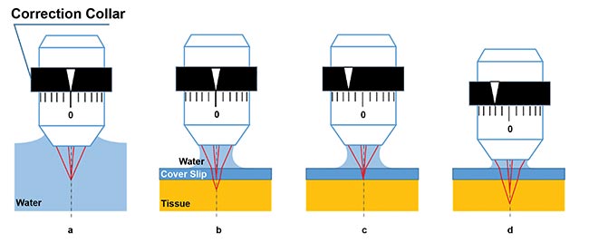
Figure 1. Schematic figures of spherical aberration caused by cover glass or tissue, and the effect of correction collar adjustment. Ideal focus happens when a water-dipping objective is immersed in water; paraxial and peripheral light rays focus to the same point. There is no spherical aberration (a). Focus with spherical aberration: When the surface of tissue is observed under a cover of glass with water immersion, refraction occurs at the boundaries between water, glass, and tissue, which causes spherical aberration (b). Spherical aberration is compensated by adjusting the correction collar (c). With the correction collar still at the previous setting, as in c, spherical aberration occurs again when the focal plane is moved to a deeper position within the sample (d). Courtesy of Hiromu Monai, Hajime Hirase, and Atsushi Miyawaki/RIKEN BSI-Olympus.
With multiphoton microscopes, observation depths can exceed several hundred micrometers. Spherical aberration can greatly degrade the focus at these depths if not properly compensated. A tighter focal volume directly translates to higher resolution, but also higher light intensity at the focus.
Multiphoton excitation is a nonlinear process where greater excitation intensity delivers more signal for the same total laser power. Proper adjustment of the objective correction collar leads to brighter and sharper images. However, the optimal position of the correction collar depends on the refractive index profile of the sample, the thickness of the cover glass, and the depth of the focal plane. When capturing images at multiple locations in a specimen, it may be necessary to adjust the correction collar many times.
Properly setting a correction collar during image acquisition can be challenging because each adjustment slightly alters the effective focal length of the objective
lens (Figure 2a). In addition, manual operation of a correction collar can be clumsy in the typical darkroom environment where multiphoton microscopes are operated. These issues make it completely impractical to manually adjust a collar for more than a single position during volume acquisition of z-stack images. In such situations, it is advisable to settle for an intermediate collar position that is optimal at one plane of the z-stack, but perhaps less so at other depth planes.
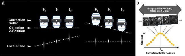
Figure 2. When conventional objective collars are rotated, the focal plane also changes (a, left). Objectives can maintain the focal plane by automatically
changing the Z-position of objective according to the rotation angle (a, right). Finding the optimal correction collar angle (θopt): A contrast curve is determined
by calculating the contrast value of each acquired image at various correction collar angles. The optimal correction collar position is calculated by determining
the peak of this contrast curve (b). Courtesy of Hiromu Monai, Hajime Hirase, and Atsushi Miyawaki/RIKEN BSI-Olympus.
Objective systems can greatly simplify spherical aberration correction with a computer-controlled, motorized correction collar system. Actuation of the collar is automatically coordinated with the microscope focus motor. As the correction collar is rotated, the objective Z-position is also adjusted to maintain a consistent focal plane (Figure 2a).
Software control not only simplifies direct user operation, but also facilitates automated collar optimization based on objectively measured quantities, such as image contrast (Figure 2b). Further, optimal settings recorded at various depths can be used to automatically drive the correction collar during a z-stack acquisition. Such automation makes it easier to consistently capture bright and high-resolution images at every depth.
Automated correction collars
Figure 3 shows two-photon-excited fluorescence images of beads embedded in a gel that simulates the refractive index and light scattering coefficient of mouse brain tissue. These results demonstrate the image quality improvement introduced by spherical aberration correction. The top row of images shows the gradual degradation of axial resolution as the observation region is advanced from the top of the sample down to 800 µm deep, without adjusting the correction collar.
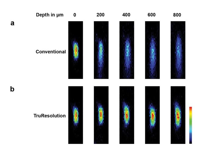
Figure 3. Fluorescent microbeads (φ200 nm) in a gel that simulates the optical characteristic of live mouse brain tissue (refractive index: 1.36, light scattering coefficient: 43 cm−1) excited at 960 nm with constant laser power (used for all images). Microbead XZ images acquired at various depths using automatic spherical aberration compensation (a). Microbead XZ images acquired at various depths using a fixed correction collar initially adjusted for optimal imaging at the surface of the gel (b). Image brightness scales are normalized at each depth. Courtesy of Hiromu Monai, Hajime Hirase, and Atsushi Miyawaki/RIKEN BSI-Olympus.
Aside from the obvious smearing of the images along the Z axis, the decrease in peak intensity with depth is also notable. In contrast, automatic collar adjustment delivers a more consistent compact focal spot across the various depths.
Demonstrated in Figure 4 are two-photon-excited fluorescence images acquired in vivo from the sensory cortex of an anesthetized mouse prepared with a glass cranial window. The total depth of the z-stack is 1.1 mm (Figure 3a). An image slice taken at 550 µm (Figure 3b) shows the brightness and resolution improvement when a system is enabled to continually adjust the correction collar through the stack, as opposed to keeping it fixed at the surface, the way one might with a manual collar.
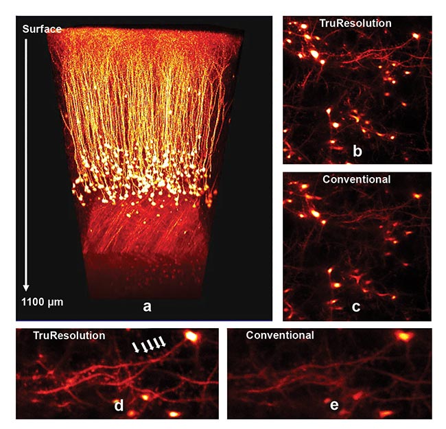
Figure 4. In vivo observation of sensory cortex in an anesthetized mouse (Thy1-YFP-H mouse, sensory cortex) prepared with a glass cranial window. 3D rendering of image z-stack, 1.1 mm thick (a). Image section at Z = 550 µm, actively using automated correction collar (b). Image section at Z = 550 µm with collar fixed to a position optimal at the top of the z-stack (c). Detail of b showing dendritic spines (white arrows) (d). Detail of c (e). Images in this study were captured using an Olympus FV30-AC25W TruResolution objective lens (25×, 1.05 NA, 2-mm working distance, water immersion). Courtesy of Hiromu Monai, Hajime Hirase, and Atsushi Miyawaki/RIKEN BSI-Olympus.
The structural morphology of submicron features, such as dendritic spine heads and necks, are more clearly captured when the optimal collar setting is applied. The characterization of dendritic spines is of particular interest to neuroscientists who study learning and memory. It has been suggested that the growth and remodeling of spines may be how experience and learning manifest in the brain.
An automated correction collar is also useful for cleared tissue samples. Refractive index varies greatly between different tissue-clearing techniques and can even vary between specimens that have been applied with the same technique. Attention to the correction collar position is vital to capturing high-quality images through the large volumes typical of cleared tissue. An ideal objective lens for this type of application would combine a long working distance with an automated collar that accommodates a wide range of refractive indices.

Proper adjustment of an objective correction collar leads to brighter and sharper images. Shown are images of microglia 100 mm deep in a live mouse visual cortex without collar correction (left) and with collar correction (right) that better resolves fine filopodia-like protrusions. Courtesy of Mitchell Murdock/
Massachusetts Institute of Technology.
Figures 5a and 5b compare images acquired with and without automated correction-collar control through a 4-mm-thick section of a mouse brain cleared using ScaleA2. The optimal collar setting yielded sharper images with brighter contrast throughout the volume compared to images captured with an arbitrary collar position. Figure 5b particularly exemplifies the considerable improvement in image resolution and brightness that is possible when the correct collar setting is used to minimize spherical aberrations.
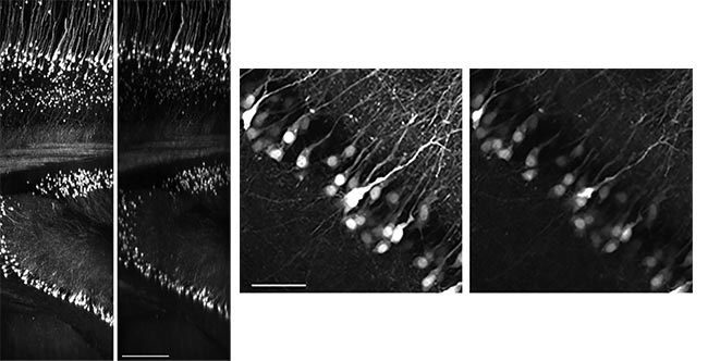
Figure 5. (Images on left) Mouse brain (Thy1-YFP-H mouse) cleared with ScaleA2. XZ image
of a 4-mm z-stack: First image was acquired after determining the best correction collar setting;
second image was acquired using an arbitrary correction collar position. Scale bar: 500 µm.
(Images above) Maximum projection of XY images from 100-µm thickness at a depth of 2.7 mm: First image was acquired at the optimal correction collar position; second image was acquired using an arbitrary correction collar position. Scale bar: 100 µm. All images were acquired with 960-nm excitation at the same laser power through an Olympus FV30-AC10SV TruResolution objective lens (10×, 0.6 NA, 8-mm working distance, multi-immersion). Courtesy of Hiromu Monai, Hajime Hirase, and Atsushi Miyawaki/RIKEN BSI-Olympus.
These deep imaging results demonstrate how automated computer control of a motorized correction collar can improve multiphoton imaging under a variety of challenging observation conditions. These innovations enable the capture of bright, high-resolution 3D images by minimizing spherical aberration in a multiphoton microscope.
Meet the author
Carlo Alonzo, Ph.D., is product manager for multiphoton microscopy and custom solutions in the Scientific Solutions Group at Olympus Corp. of the Americas. He assists scientists in identifying and understanding enabling technologies to support research goals. His interest in biomedical optics drew him to the academic community in Boston, where he spent several years immersed in research utilizing multiphoton microscopy. He has a doctorate in physics from the University of the Philippines, and pursued postdoctoral training at the Technical University of Denmark; email: [email protected].