Larger and more complex optical systems, particularly in satellites and high-power lasers, are creating demand for large-aperture interferometers.
ERIK NOVAK, 4D TECHNOLOGY CORP.
Laser Fizeau interferometers are the workhorses of optical testing. With proper configurations and accessories, these instruments enable characterization of flats, prisms, concave and
convex lenses, and even aspheric elements. While many laser Fizeau systems produce output beams that are 6 in. or less in diameter, the increased production of telescopes, satellites, high-power lasers, and other novel optical systems are driving a greater need for systems with output apertures larger than 12 in. (300 mm) in diameter.
In the past, large Fizeau systems have been designed in one of two ways: Either they have been custom-built with unique housings and optical elements, or they have combined smaller interferometers with off-axis, air-table-mounted optical beam expanders to achieve the necessary aperture size.
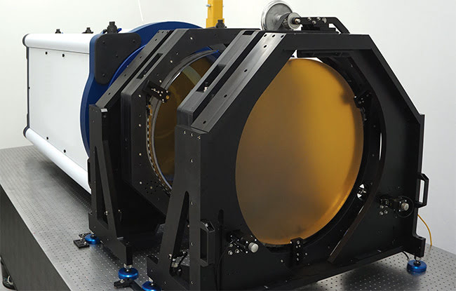
Large Fizeau interferometers (24 in./600 mm) are becoming more commonplace. Courtesy of 4D Technology Corp.
Today, modern materials, better design methods, and software engines reduce complexity, improve precision and repeatability, and greatly enhance the usability of large-aperture laser Fizeaus across a variety of applications. Advantageous design considerations now include fold-free, thermally compensated beam expansion, a removable 4-in.-aperture interferometer engine, autofocus, high-powered alignment lasers, and even automated software for precision and spatial resolution verification.
There are a number of critical elements that designers must consider for next-generation, large-aperture interferometers, particularly the 24-in. (600-mm) aperture system, which is among the most challenging. Incidentally, an understanding of the 24-in. system can be beneficial to those working with smaller systems because the 24-in. system models ways to reduce environmental effects, improve acquisition times and robustness, and more rapidly gather and manage higher-quality data for end users.
Mechanical design
The optical components of any measurement system are, of course, extremely important. However, even the best-designed optics will fail to provide consistent, high-quality data if they become misaligned or defocused as a result of external factors such as temperature changes, mechanical stress, or vibration. Some 24-in. systems — such as those produced by WYKO Corp. to measure
the optics for Lawrence Livermore’s National Ignition Facility (NIF) — were custom-built, with each optic hard-mounted to a large air table. While this system produced unprecedented performance 20 years ago, its design prevented portability, it was susceptible to small misalignments because of multiple system folds, and it was difficult to service on account of its myriad custom components.
In 2017, 4D Technology Corp. had an opportunity to design and build the next-generation large-aperture systems for measuring high-power laser optics and other tight-tolerance components for a new laser fusion research effort in China. A bottom-up approach was selected to ensure the best possible performance, stability, and reliability. The 4-in. (100-mm)-aperture AccuFiz laser Fizeau — which already had diffraction-limited imaging, a very compact and lightweight design, and a very high instrument transfer function (ITF) for a commercial interferometer system — was chosen as the fundamental measurement engine.
Because the AccuFiz was a standard high-volume system on its own, combining it with a beam expander ensured that most of the system’s performance was already qualified to a high degree and would be easily supported into the future. The goal was to create the best possible beam expander while preserving the AccuFiz’s desirable characteristics and at the same time create a simple modular design for the overall large-aperture systems.
Making an on-axis beam expander was an early design decision. This meant the optical axis of the AccuFiz engine itself was centered on the optical axis of the beam expander. This decision proved important for several reasons. First, the off-axis fold mirrors that many systems use can change the polarization of the light. Often, and especially with high-power laser optics, polarization has to be known and, in fact, has to be changed from measurement to measurement for full component characterization. Second, with an on-axis kinematic mount for the standard Fizeau interferometer on the beam expander, the small-aperture system could be readily removed for high-resolution, small-field-of-view measurements and then replaced as necessary for measuring the full 600-mm aperture. Further, with the AccuFiz connected only to the beam expander — and no parts hard-mounted to the underlying air table — the entire system would be simple to install and to move. While the 24-in. systems produced for the NIF program took one to two weeks to fully install and qualify, this design could be unpacked and running in just a few hours, with full qualification in several days, limited mostly by the time required for long-term stability tests (Figure 1).
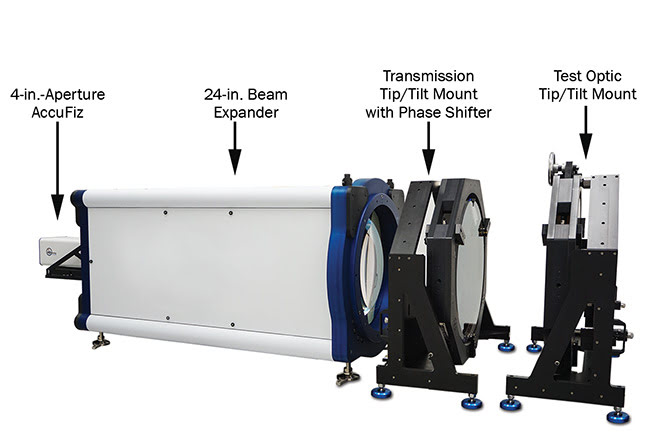
Figure 1. Overall mechanical layout of the new 600-mm-aperture laser Fizeau. Courtesy of 4D Technology Corp.
The 600-mm beam expanding collimator was quite heavy. To ensure that mounting the optic would not misalign the lens, deformation of the support elements that hold the optic in position (caused by thermal loads) had to be minimized. Also, to prevent ambient vibration from adversely affecting system performance, a resonance frequency of over 50 Hz, which is typically desired, was used. Thermal effects had to be modeled to guarantee proper operation in standard laboratory environments.
Extensive CAD modeling was employed throughout the design process to determine the best materials and geometry. Ultimately, the latest carbon fiber materials were chosen for the support columns and the specialized connecting elements, which contributed to stability. The natural frequency of the structure was pushed above 50 Hz, and thermal stability was brought below a 1-µm total length change, over the 2-m structure, with a 10 ºC temperature shift, creating unprecedented immunity to the ambient environment (Figure 2).
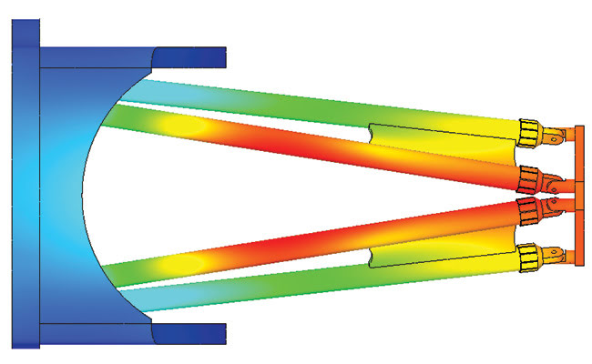
Figure 2. CAD model output of static deformation under load. Red areas are the most deformed but exhibit fewer than 6 μm of total change in the 2-m-long structure. The curved elements connecting the support columns are critical for best performance. Courtesy of 4D Technology Corp.
Ease of use and flexibility of the system were maximized by incorporating several other mechanical design considerations (Figure 3). First, the phase shifting was accomplished by mechanical phase shift of the piezoelectric transducer (PZT). This meant that, unlike with wavelength-shifting interferometric systems, no recalibration would be necessary as the cavity changed. Mechanical phase shifting also meant that the standard laser could be readily swapped with a variable-coherence laser via the fiber port on the 4-in. AccuFiz engine. With variable coherence, the interferometer is able to measure plane-parallel optics without any effects from the optics’ back-side reflection. Thus, homogeneity and other measurements are much simpler than on most interferometric systems.
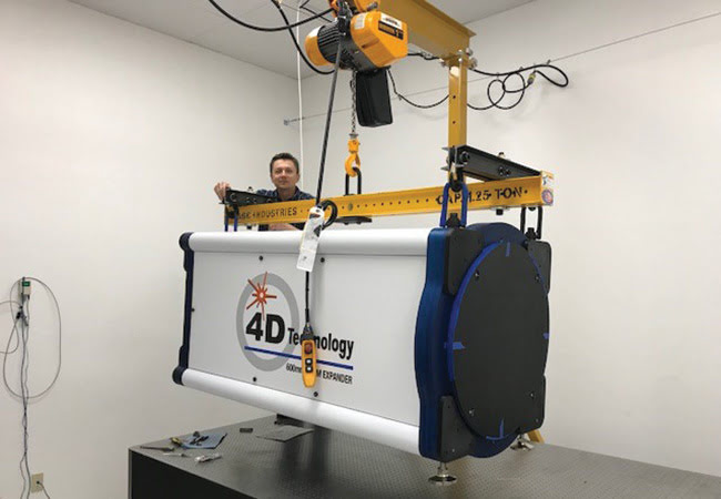
Figure 3. A monolithic design allows the entire system to be moved and shipped without disassembly. Courtesy of 4D Technology Corp.
The transmission flat and phase shifter were also mechanically separated from the rest of the structure. This made swapping elements for a three-flat test very simple and allowed the cavity between the transmission flat and the return flat to be readily reconfigured for different tests. The flats themselves were mounted in an ultralow-stress, double-chain mount. This mount allowed for rotation of elements for three-flat tests and ensured that minimal stress would be placed on the optics, maximizing interferometer accuracy.
The final step was hard-mounting a high-power alignment laser, which could be positioned anywhere within the field of view, to the front of the system. Hard-mounting the alignment laser meant that lining up optics for testing would be simple and quick, minimizing potential damage from handling such large, expensive elements (Figure 4).
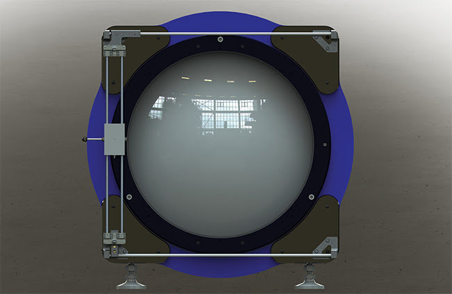
Figure 4. Gantry-type alignment laser setup. The gray rectangle contains an alignment laser that can be moved to any part of the 600-mm aperture. Courtesy of 4D Technology Corp.
Characterizing optics
When qualifying high-quality optics, it is important to consider several critical characteristics of the interferometer that affect the accuracy of the measurement results. The first is the overall quality of the cavity, which is formed by the return flat and the transmission flat, and which ultimately determines the base accuracy of the interferometer. A lower-quality cavity can be compensated via a three-flat test, which separately determines the shape of each element in the cavity. However, as the name implies, such a test requires three total flats: two transmission flats and one return flat. But the test is time-consuming and costly because an additional large transmission flat is needed. Thus, if a low-error cavity can be achieved to start with, acceptable results can be obtained without a three-flat test.
With no off-axis elements, and with an optimal lens design and the mechanical design choices mentioned above, the system was able to achieve better than λ/20 peak-to-valley cavity quality for a 1064-nm wavelength, 600-mm aperture (Figure 5).
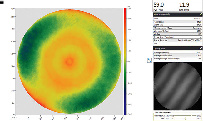
Figure 5. Cavity quality is better than λ/20 peak to valley in this 1064-nm wavelength, 600-mm interferometer. Courtesy of 4D Technology Corp.
Two other critical metrics, which involve the spatial frequency response of the system, are necessary for characterizing today’s precision optics. A poorly designed system will not properly measure high-frequency components, and even a well-designed system may produce erroneous data if the test optic is defocused. Also, any high-frequency structure in the optics of the interferometer itself can mask the ability to measure such structures in the test pieces.
To guarantee proper performance, an auto-focus routine can be implemented whereby the customer can automatically achieve best focus on any element being measured. The algorithm examines the contrast of an intensity step within the field of view, compares it to the theoretical result, and changes focus until the two most closely match. Once best focus is achieved, the system can automatically calculate and display the ITF, which graphically shows how close to ideal the structures of a given frequency will measure. A 600-mm aperture system can achieve 70 percent fidelity to beyond 2 lines/mm of spatial frequency, readily exceeding the performance of any other systems of this aperture size (Figure 6).
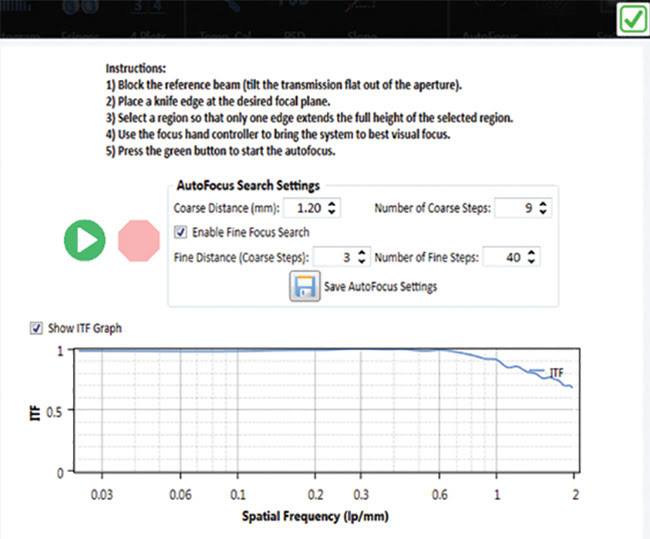
Figure 6. Autofocus function and automatic ITF (instrument transfer function) plot ensure the highest quality measurements for any given setup. Courtesy of 4D Technology Corp.
For quality assurance, software was built into the system to calculate the power spectral density (PSD) of measurements. Many optical systems, but particularly high-power laser systems, are susceptible to structures of certain spatial frequencies, mostly of higher frequency range; it is important, therefore, to ensure that such structures are not present. The 600-mm system in question was required to have no structure in the basic cavity measurement above a frequency of 0.1 γ−1.55 from frequencies of 0.1 lines/mm to 0.4 lines/mm. The software allows entry of the trendline equation and calculates the PSD over the full range, showing that the system exceeded the specification, again ensuring proper operation with minimal customer interaction (Figure 7).
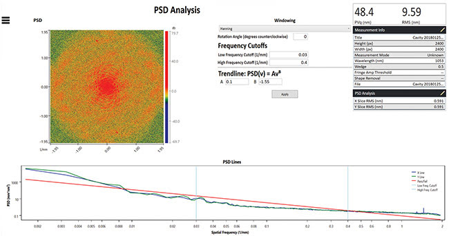
Figure 7. Software calculation of PSD (power spectral density). Courtesy of 4D Technology Corp.
In general, improvements in interferometry over the past few decades have come from advanced software that improves phase unwrapping, speeds measurements, and provides additional analysis capability. But to further improve the state of the art in building interferometers, the use of modern modeling and mechanical design capabilities and materials, as well as a user-centric approach to hardware design, are critical.
Incorporating the diagnostic tools of visual representation of the calibration quality, automatic calculation of the system ITF, and PSD reporting give confidence that measurement quality is meeting specification each and every time. Providing capabilities such as easily switchable laser source modules, highpowered alignment beams, and autofocus significantly improves ease of use,
minimizes time to results, and guarantees that resources can be spent optimizing fabrication instead of setting up measurements. The elements described apply not just to the largest systems, but to the entire range of aperture sizes, ensuring the best capabilities whatever the part under test.
Meet the author
Erik Novak is director of business development at 4D Technology Corp. He received his Ph.D. in optical sciences from the University of Arizona, under James Wyant, in 1998. Novak has been developing metrology instrumentation for more than 24 years.
4D Technology was a recipient of a 2019 Prism Award.