
EMCCD Technology Moves Beyond Standard Products
Custom sensors can satisfy particular performance and configuration requirements for applications such as astronomy, airborne reconnaissance and environmental monitoring.
Mark Robbins, e2v
The ultralow-noise and high-speed capability of electron-multiplying CCD (EMCCD) technology has improved low-light imaging over a wide range of applications, from single-molecule detection in the life sciences to imaging for covert operations undertaken by military special forces. Many of these requirements are met using off-the-shelf products. However, custom sensors also have been developed to meet the needs of specific applications
For example, the distorting effects of the atmosphere limit the performance of ground-based astronomical telescopes. On professional instruments, an adaptive optics technique can correct for the effects of atmospheric turbulence. A typical system requires a wavefront sensor such as a Shack-Hartmann. In a Shack-Hartmann system, a real or artificial guide star is focused on an image sensor using a lenslet array to sample across the wavefront. Each lens of the array focuses a spot onto a different part of the sensor. The wavefront error can be calculated from the position of the focused spots and a deformable mirror adjusted accordingly.
The next generation of adaptive optical instruments for 8- to 10-m telescopes requires much greater sampling for correction of the wavefront error in both the spatial and temporal domains. The greater sampling implies fewer photons per pixel than are detected currently. A read noise significantly less than 1 e– is needed to achieve the required accuracy at the extremely low signal levels present. This, together with the need to sample at least 240 × 240 pixels at a frame rate of 1.5 kHz, makes the application ideally suited to EMCCD technology. The European Southern Observatory and JRA2 Opticon network have funded e2v technologies Ltd. to develop a compact packaged Peltier-cooled sensor to meet the requirements of this new generation of wavefront-sensing instruments (Figure 1).
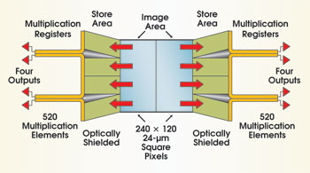
Figure 1. The EMCCD for the wavefront-sensing instrument uses eight electron-multiplying (gain) registers to obtain subelectron noise at a frame rate of 1.5 kHz.
To obtain a high frame rate from the device, eight multiplying outputs are used in split frame transfer configuration. Back-illumination is employed for optimum sensitivity, and a speculative variant using thicker silicon is being assessed for improved sensitivity in the near-infrared. A version with a novel on-chip shutter also is being developed for pulsed laser guide star applications. The sensors have been manufactured and are awaiting detailed characterization (Figure 2).
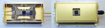
Figure 2. The wavefront sensor is shown before and after sealing into the Peltier pack. The window material is high-grade sapphire.
Airborne reconnaissance
The visible sensors currently employed in high-speed, in low- and medium-altitude and in standoff airborne reconnaissance applications are conventional, high-performance linear CCDs used in a push-broom configuration. In this application, linear sensors have significant operational benefits over standard interline- or frame-transfer devices. Silicon CCDs are used for the visible and near-infrared regions of the spectrum, and the wavelength range of the system can be extended by the addition of an integrated infrared line-scan camera.
Thales Optronics evaluated EMCCD technology for use within its system. An aluminum mask was applied to a standard frame transfer EMCCD sensor (L3Vision CCD65) to optically shield all but one row. The sensor with the supplied drive electronics could mimic the operation of a linear CCD running at a rate greater than 1400 lines per second.
The camera module was installed in a reconnaissance pod that was mounted on a jet aircraft together with the conventional visible and infrared units. Direct performance comparison of the ground-resolvable distance was not possible because of the various fields of view, but sensitivity comparisons could be made. The EMCCD module could be used at light levels significantly below those of the conventional CCD camera. Under twilight conditions, for example, the detector produced high-contrast, high-resolution images, whereas the images from the conventional sensor were lost in the noise. Under starlight conditions — a light level more than four orders of magnitude lower than that of twilight — the module continued to provide useful imagery (Figure 3). The EMCCD images give sharper definition to the edges of man-made objects and can resolve finer textural differences, making the images easier to interpret.''
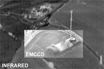
Figure 3. Flight trials compared the EMCCD with infrared modules under starlight conditions.
These initial trials have led to a design study for a novel linear EMCCD sensor that would provide optimized performance both during the day and at night. One of the benefits of the technology is that simply adjusting the amplitude of the clocks sets the level of on-chip multiplication gain. Thus, at high illumination levels, the multiplication gain can be set to unity and can be increased when the light level falls, achieving a high dynamic range.
When optimizing the ground-resolvable distance, both noise and pixel size must be considered. At high light levels, the pixel pitch dominates the achievable resolution, whereas at low light levels, the effects of photon shot noise become dominant. Therefore, one option considered was a device with multiple EMCCD outputs and with three rows. Each row would have a different-size pinned photodiode pixel, with the row having the smallest pixels used at high light levels (optimized resolution) and the row with the largest pixels used at the lowest light levels (minimum noise). The signal from the high-resolution pixels could be combined off-chip, simplifying the design. However, analysis has shown that the on-chip solution yields better performance.
Lidar instrument
The technology is also helpful for spaceborne observation of aerosols within the atmosphere for environmental monitoring. The European Space Agency has funded e2v to develop a prototype EMCCD sensor for a lidar instrument as part of a study of instrumentation for future Earth observation missions.
In this application, a pulsed laser beam is transmitted from the satellite with a typical repetition frequency of 100 Hz. A fraction of the light is backscattered from aerosols and clouds and detected at the focal plane with a time delay (3 ms approximately) resulting from the round-trip distance. This marks the beginning of the “atmospheric sequence,” where the signal is backscattered from all the atmospheric layers as the beam continues to propagate. Finally, a “ground echo” is observed from the signal reflected off the Earth’s surface (Figure 4).
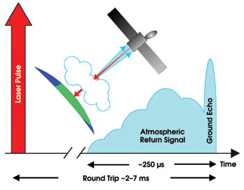
Figure 4. To perform atmospheric monitoring with lidar, a laser is pulsed, and the return signals are measured to enable the vertical profiles of aerosols, liquid water and ice to be quantified on a global scale. Observations will lead to more reliable climate prediction and to better weather forecasting.
The basic requirement was for a detector to measure the variation in brightness of a small spot of light with a sampling window of less than 1 μs. To include the expected atmospheric return and ground echo, 400 samples would be needed. Despite its high sensitivity, the detector also had to be tolerant of very large signals — for example, those from specular reflections.
The sensor is shown in Figure 5. The device is back-illuminated to enhance sensitivity and to enable operation in the ultraviolet. The image section consists of a central 6 × 6 20-μm-square pixel array that is flushed continuously of unwanted signal until the expected time of arrival of the atmospheric return. At this point, the signal acquisition sequence commences.
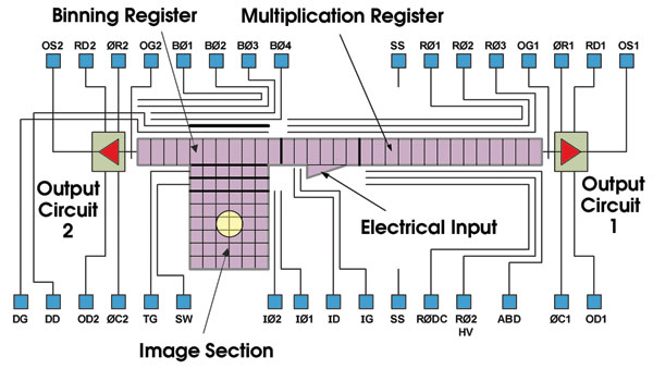
Figure 5. In the lidar sensor, a signal from the image section is binned into a single gain register element. The electrical input is used for testing and for gain calibration.
For each sample, the signals from all pixels are combined and clocked into the multiplication register. For the characterization of the device, 100 background samples were taken, followed by the 400 samples that would contain atmospheric information. These samples were taken at a rate of 1.5 MHz, and the sequence was repeated every 10 ms.
The measured output from the device is shown in Figure 6. Here a range of atmospheric return signals were simulated by appropriately pulsing a pair of LEDs to inject charge during the acquisition sequence, from a mean input signal of 0.2 e– at the start of the sequence up to 69 e– per sample at the end. The ground echo was simulated using a laser diode. The results from this development work have shown that EMCCD technology is appropriate for this demanding application and may be considered for future missions.
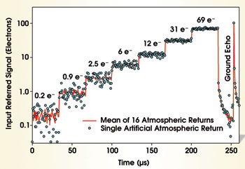
Figure 6. The measured response of the lidar sensor to a simulated atmospheric return and ground echo at a data rate of 1.5 MHz is shown.
Meet the author
Mark Robbins is a predevelopment technology manager in the space and scientific imaging business unit of e2v technologies Ltd., Chelmsford, UK; e-mail: [email protected].
/Buyers_Guide/Teledyne_e2v_-_UK/c4580