Tasso R.M. Sales, RPC Photonics, Inc.
Uniform illumination over a certain target
area is a common requirement in many applications, and oftentimes schemes must be
devised to ensure that this requirement is achieved. In display systems, for example,
light that illuminates a viewing interface such as a screen must appear uniform
and devoid of any distracting image artifacts. Depending on the particularities
of the system, different approaches must be developed to provide uniform illumination
without sacrificing efficiency.
Side-illuminated backlit displays use painted dots and microstructures
to extract guided light in a controlled fashion so that the display is visually
uniform; lithographic illumination systems often use fly’s eye microlens arrays
to generate uniform illumination, sometimes in combination with additional diffusers
and/or motion to minimize the diffraction artifacts induced by the periodic lens
arrays; laser displays make use of optical diffusers for shaping and uniform light
distribution as well as speckle management; general lighting has routinely relied
on simple diffusers and prismatic films that, although not the most efficient or
aesthetically pleasing, are inexpensive and commonly found in light fixtures.
A frequent approach to uniformly illuminating a target uses a
diffusing element in the optical path to spread and homogenize the incident illumination
and provide the desired degree of uniformity. The requirements for the diffuser,
or diffusers, depend upon a number of factors, such as the source properties (primarily
spectrum, divergence and coherence), as well as on the performance goals, which
depend strongly upon the application. We are particularly concerned with applications
that require some sort of light shaping, either in intensity or distribution. For
this type of application, optical performance is critical, and only a handful of
diffuser technologies can be brought to bear.

Shown here is a microlens array in fused silica.
Among the available options, band-limited diffusers are unique
because of their highly desirable qualities and good performance. Band-limited diffusers
are defined as diffusers that scatter light within a well-defined angular range,
usually – but not necessarily – with uniform intensity. An ideal band-limited
diffuser attains 100 percent of the diffuse light within its band limit; in practice,
however, it has been difficult to come close to this goal for a variety of reasons.
Here we will review issues related to common diffuser technologies, typical performance
associated with the technology and its precision in comparison with the band-limited
ideal. We will also discuss recent advancements in microlens diffusers engineered
to attain nearly band-limited performance.
Band-limited diffusers
The concept of a band-limited function is best known in the framework
of linear systems theory, particularly with regard to signal recovery from sampled
data1 where band-limited functions have interesting properties. A band-limited function
has nonzero values only within a finite domain. Outside of this domain, the function
is identically zero. In the context of diffusers, the concept applies directly so
that in the far field, or at the focal plane of a lens, the diffuse light is confined
to a certain angular range with little or, ideally, no energy outside of that range.
Figure 1 illustrates an ideal band-limited diffuser in the geometrical
optics limit where all of the incident illumination is contained within a cone angle Θ. Both blue and red curves represent band-limited diffusers. The case of uniform
illumination (blue curve), however, plays a particularly important role in many
applications, and for this reason, we will focus on uniform band-limited diffusers.
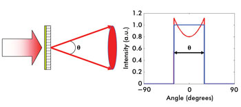
Figure 1. In an ideal band-limited
diffuser, all light is scattered within a certain angular range, Θ.
Evidently, the geometrical limit is only an approximation, and,
because of diffraction, the intensity fall-off at the edges of the intensity profile
always has a finite extent. This depends on the nature of the surface features that
define the diffuser, assuming that the incident illumination is collimated. In any
case, the concept of a band-limited diffuser is simply extended to include the intensity
fall-off so that, in the best possible scenario, the fall-off is limited only by
diffraction.
Given the importance of uniform illumination, it is no surprise
that band-limited diffusers have been the focus of continual, if sporadic, investigation.
Significant advances in the understanding of the fundamental properties of band-limited
diffusers seem to have started in the early 1970s, and research continues to this
day. During this period, however, the goal of producing a band-limited diffuser
has remained elusive.
Existing solutions
One of the earliest attempts at implementing a band-limited diffuser
was the diffractive diffuser, which can create very uniform diffuse patterns with
general distributions. However, it is intrinsic to diffractive elements that a certain
fraction of the incident illumination spills into diffraction orders beyond the
target region of interest. In the case of binary elements, at least 20 percent of
the light is lost to higher diffraction orders. If the diffuser is produced with
a continuous-phase function, the losses become much lower, but even in this case,
typically at least 5 to 10 percent is lost to higher diffraction orders (Note that
these figures do not include Fresnel losses). We can therefore say that, although
a diffractive diffuser can provide uniform illumination, it is not band-limited,
with the continuous-phase element coming very close.
A limiting issue with diffractive diffusers, however, is that
they are often restricted to monochromatic illumination and relatively small spread
angles, unless one can deal with a strong zero order, a bright center spot collinear
with the incident illumination. Because of deviation from the design wavelength
or fabrication errors, diffractive elements commonly display the presence of a zero
diffraction order that is much stronger than any other order in the diffraction
pattern, and may or may not be eliminated in practice.
Refractive diffusers, on the other hand, are fundamentally free
of the intrinsic losses associated with high-order diffraction and zero order, and
are thus the best candidates for band-limited behavior. Simple examples of refractive
diffusers include ground glass and holographic diffusers created by exposing photosensitive
materials to laser speckle. These diffusers have been around for quite some time
but generate Gaussian scatter and therefore do not have a uniform scatter region
or well-defined cutoff for the diffuse light and are thus not band-limited. Just
a few decades ago, researchers at Kodak would comment2 that “no known random
phase diffuser is band-limited.” This includes diffractive diffusers, which,
strictly speaking, are not random, and holographic diffusers, which are obviously
not band-limited.
Since the early work at Kodak and elsewhere, not much had happened
until recently, when microlens-based diffusers became commercially available.3 Alternative
concepts also have been proposed4 such as a distribution of linear facets that are
randomly combined to spread light over a specific angular range. Each facet scatters
into a specific direction; by imposing an upper limit to the slope angles in the
ensemble, one can theoretically guarantee band-limited behavior. By further ensuring
the appropriate distribution of facets over the angular range of interest, one can
produce uniform illumination.
The approach does provide, at least in principle, band-limited
behavior, and some experimental demonstration can be found in the literature.5 However,
because each linear facet corresponds to a specific angular direction, this type
of diffuser would seem to require a large input beam size to sample a sufficiently
large number of facets so that uniform illumination could result over some specified
angular range. Making the linear facets small minimizes the requirements for a large
beam but runs into manufacturing issues.
Microlens-based engineered diffusers
Microlens arrays are used in a great number of applications, and
in certain instances, they are also used for beam shaping and diffusion. However,
because microlens arrays are periodic, there is a limitation in the achievable shaping
capabilities as well as in the diffraction effects that result from the regular
arrangement of the microlenses. The microlens element itself, however, provides
a basic component from which general band-limited diffusers can be built.
In recent years, we have introduced a class of microlens-based
diffusers3 – also referred to as engineered diffusers – that provide
not only homogenization but also general shaping capabilities. Each microlens unit
in an engineered diffuser is defined by a certain number of parameters, such as
a radius of curvature and a conic constant that are randomized to create the diffuser.
Unlike common diffusers, however, engineered diffusers are created deterministically,
such that each microlens element is individually designed and fabricated to produce
a certain scatter pattern with a controlled intensity profile.
The design concept behind engineered diffusers can be described
in simple terms. The prescription for the set of lenses that comprise the diffuser
is defined, including feature sizes and slope angles based on the scatter requirements.
These parameters are typically defined in terms of probability distribution functions
that specify the likelihood that a certain lens will assume a specific prescription.
The next step is the spatial distribution of the microlenses to create the diffuser
surface structure according to probability distribution functions. An example of
a commercially available engineered diffuser that shapes an incident beam into a
20° square pattern is shown in Figure 2.
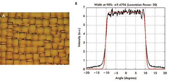
Figure 2. Shown is the surface pattern of a diffuser that generates a square pattern (A)
and its measured intensity profile (B).
The intensity profile (Figure 2B,) was measured in the far field
with a detector large enough to average enough speckles and reveal the envelope
of the intensity distribution. The intensity profile can be described by a Lorentzian
profile – the red curve in Figure 2B – given by
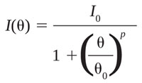
where I0 is a constant, 2Θ0 is the full width half maximum, and
p is a number directly related to the flatness of the intensity profile. For the
plot shown in Figure 2, p = 30 and Θ0 = 11.5°. For p = 2, one finds the usual
Lorentzian function. For p >2, the function is sometimes referred to as a “super-Lorentzian”
with power p. The parameter p provides an indication of the flatness, or uniformity,
of the super-Lorentzian intensity profile, Figure 2. The larger the parameter p,
the flatter will be the intensity profile and the narrower the fall-off region.
For uniform diffusers, the steepness of the fall-off depends directly on the microlens
feature size. For the diffuser shown in Figure 2, the lens feature sizes are ≤160
μm.
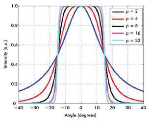
Figure 3. Shown are super-Lorentzian curves for Θ0 = 15° and various power values.
Two items are readily noticeable from Figure 2. First, although
the surface pattern on Figure 2B is clearly not regular, an underlying grid pattern
seems apparent. Secondly, the super-Lorentzian fit matches nicely the flat portion
of the intensity profile but not the bottom portion, toward wider angles. The effect
of an underlying grid in the diffuser surface reveals itself in the diffuse pattern
as diffraction artifacts that are particularly obvious with coherent sources such
as lasers. A small illuminating beam size further emphasizes the nonuniformity.
Examples of these artifacts are seen in Figure 4. As the beam size increases, the
visibility of these artifacts is reduced but not completely eliminated.
The mismatch in the wide-angle fit, Figure 2B, is caused by scatter
losses due to light falling outside the target. These losses originate from steep
slopes between adjoining lenses. Each lens has a unique surface prescription that
is generally distinct from another lens.
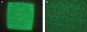
Figure 4. The scatter pattern from a diffuser that shapes a laser
beam into a square pattern is
pictured. The diffuser surface has some underlying periodicity that
shows up as
diffracting artifacts such as lines (A) and, on a finer scale, dots (B)
with apparent
local periodicity.
Consequently, the boundary between lenses generally contains discontinuities
that spread light into wide angles outside the target and lead to the observed deviation
from the super-Lorentzian fit. It clearly also reduces the system efficiency. Estimates
place the amount of lost light to wide-angle scatter at approximately 10 to 15 percent,
depending on the diffuser design, feature sizes and conditions of fabrication.
Band-limited engineered diffusers
Recent improvements in design and fabrication techniques have
led us to develop a diffuser concept that considerably advances the state of the
art in the production of microlens-based diffusers. At the root of these improvements
is the effort to eliminate any underlying periodicity in the spatial distribution
of the microlenses and to eliminate lens mismatches that lead to wide-angle scatter,
thus maximizing the use of available light.
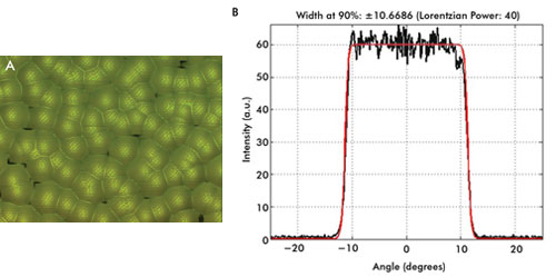
Figure 5. Shown is an example of a band-limited engineered
diffuser profile (A) and its measured intensity profile
(B).
The measured performance of this new class of diffusers comes
much closer to the band-limited ideal without the presence of diffraction or image
artifacts, which should be particularly significant not only for coherent illumination
but also for incoherent illumination such as LEDs, because of the higher efficiency.
An illustration of the surface structure of this band-limited engineered diffuser
is shown in Figure 5.
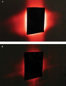
Figure 6. A typical engineered diffuser produces a square
pattern (A), whereas a band-limited
engineered diffuser shows considerably less light loss outside the
square pattern
(B).
The intensity profile shown in Figure 5B indicates much improved
super-Lorentzian behavior over the entire range of angles with p = 40 and lens feature
sizes ≤160 μm. To further illustrate the higher efficiency of the band-limited
engineered diffuser, Figure 6 shows a visual comparison of the light scattered outside
of the target, where it seems clear that the new generation of diffusers significantly
increases the utilization of light.
Finally, the careful randomization of the diffuser surface structure
also creates a scatter distribution that is devoid of artifacts. In the case of
coherent illumination, it gives rise to the typical uniformly random speckle pattern
expected from random diffusers, as illustrated in Figure 7. For reference and side-by-side
comparison, 4B is repeated in 7B.
It is now nearly half a century since the first significant efforts
started in the understanding and fabrication of band-limited diffusers. Since then,
we have developed a better understanding of the theoretical requirements for band-limited
diffusers. The relatively recent introduction of microlens-based diffusers, in the
form of engineered diffusers, came a step closer to the band-limited ideal, although
they are not perfect.
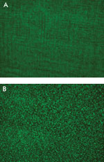
Figure 7. Shown is a speckle comparison of a standard (A) and a
band-limited (B) engineered diffuser.
The new generation of microlens diffusers that is now being unveiled,
as described here, brings the band-limited diffuser idea from a purely conceptual
realm into the real world.
Meet the author
Tasso R.M. Sales is chief technology officer at RPC Photonics
Inc. in Rochester, N.Y. He can be reached at [email protected].
References
1. J.W. Goodman (1996). Introduction to Fourier Optics, 2nd ed.
McGraw-Hill, New York.
2. C.N. Kurtz, H.O. Hoadley and J.J. DePalma (1973). Design and
synthesis of random phase diffusers. J Opt Soc Am, pp. 1080-1092.
3. www.rpcphotonics.com and www.thorlabs.com.
4. E.R. Méndez et al (2004). Design of two-dimensional random
surfaces with specified scattering properties. Opt Lett, pp. 2917-2919.
5. E.R. Méndez et al (2001). Photofabrication of random achromatic
optical diffusers for uniform illumination. Appl Opt, pp. 1098-1108.