To ensure fast, error-free data transmission, connectors must conform to acceptance criteria related to backreflection and insertion loss, as well as to end-face geometry specifications.
Robert Rubin, Ultra Tec Mfg. Inc.
Optical fiber is a good vehicle for high-speed data transmission as long as light transmission is efficient — even across connector assemblies. This translates to a need to polish connector end faces to optimize performance. Increasingly, with the adoption of newer fiber configurations, as well as ever-tightening specifications, automation of the polishing process is becoming a necessity.
Early physical contact connectors required spherical forming of their flat end faces as part of the polishing procedure. These traditional techniques involved a four-step process: epoxy removal, ferrule forming, and preliminary and final polishing. These steps used aggressive materials for epoxy removal and ferrule forming, generally accomplished with diamond polishing films.
Now, however, because almost all connectors are manufactured with a pre-radiused end face, the polishing process has developed into a sequence of epoxy removal, followed by rough, intermediate and final polishing cycles. One goal is to avoid excessive disruption of the spherical surface, while still producing a good mating surface. Polished fiber optic connectors must then conform to a range of performance and geometry-based acceptance criteria.
Polishing specifications for fiber connectors fall into two categories related to performance and end-face geometry. Perhaps the most critical measures of polished end functionality are backreflection and insertion loss specifications. The latter is the amount of optical power lost at the interface between the connectors, usually caused by fiber misalignment, separation between connections (the air gap) and the finish quality of each connector end. This loss is a function of both the polishing equipment and the technique used. The current standard loss specification is less than 0.5 dB, but less than 0.3 dB is increasingly specified.
Fiber optic connectors are often specified with a backreflection of less than –55 dB and insertion loss of less than 0.3 dB. Another option is ultraphysical contact, with an angled end face.
Connector types
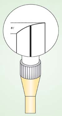
Backreflection is the light reflected back through the fiber toward the source. High backreflection can translate to signal distortion and, therefore, bit errors in systems with high data transfer rates. Common connector categories include superphysical contact, with backreflection of –45 dB; ultraphysical contact, with backreflection of ≤–55 dB; and angled physical contact, which has an 8° angle on the end face and backreflection of ≤–65 dB. Although acceptable backreflection will vary depending on the application, end user requirements increasingly specify ultraphysical-contact connectors.
Key geometric acceptance criteria include apex offset, radius of curvature, and fiber undercut or protrusion. All of these affect performance to some degree. For example, apex offset is the measured distance between the center of the fiber and the apex or highest point on the spherical surface at the connector end face. An excessive offset will contribute to high insertion loss and backreflection readings. Current accepted offset is less than 50 μm.
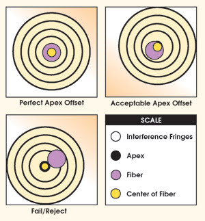
Interferometric analysis is used to measure the apex offset of fiber optic connector end faces. An offset of 50 nm or higher can limit fiber-to-fiber contact, increasing insertion loss.
The radius of curvature measures the radius generated on a connector end face. This measurement must be such that when mated with another connector, most of the compression is applied to the material surrounding the fiber (also called ferrule absorption). The typical specification range is now 8 to 25 mm. In general, the pre-radius on ferrules is maintained during polishing by using a weight to apply pressure between the connector and a resilient polishing surface, or by setting compression dimensionally. The harder the polishing surface, the larger the resultant connector radius.
Optimizing compression
A proper radius, combined with an acceptable fiber undercut, will optimize fiber-to-connector compression. The undercut measures how far the fiber is recessed inside a connector ferrule, but it also may be possible for a fiber to protrude above the ferrule. Both conditions directly result from the polishing process and can be measured with an interferometer.
Excessive fiber undercut/protrusion is usually specified as greater than ±50 nm. When connectors are mated, the ferrule material surrounding the fiber compresses, allowing fibers with an acceptable undercut or protrusion to make contact. Inadequate contact can lead to an air gap as well as unacceptable backreflection and insertion loss.
Today there are several types of connectorized fibers, the most common of which are 2.5 mm, 1.25 mm and multifiber. To ensure a proper mating surface, connector end faces must first be air-polished. This will be followed by a sequence of polishing steps that depend on the type of connector, the backreflection and the insertion loss specifications, as listed below for 2.5-mm connectors:
Multimode. Used in less-demanding applications, this three-step process would involve 5-μm silicon carbide, 1-μm diamond and a final polish film.
Single-mode ultraphysical contact. Probably the most common polished 2.5-mm connector, this offers fairly good backreflection of less than –55 dB, without the need to add an angle to the end face. The typical sequence includes a 5-μm silicon carbide pass, polishing with 3-μm aluminum oxide and 1-μm diamond, and a final polishing film.
Single-mode angled physical contact. This offers the best backreflection performance at less than –65 dB; however, there is an added processing cost because of the addition of the 8° angle to deflect backreflection to that level. This process would involve polishing with 15-μm silicon carbide, passes with 3-μm aluminum oxide and 1-μm diamond, and a final polishing film.
Regardless of the connector type, most polishing sequences begin with aggressive materials, including silicon carbide to remove epoxy and diamond lapping films for beginning and intermediate polishing. These remove both surrounding material and fiber at the same rate. The last polishing step, however, requires a less aggressive material, such as silicon dioxide, to attack only the fiber. Using a material for final polishing that is too aggressive could lead to excessive undercut. The wrong final-polish material also could cause excessive protrusion, leading to fiber chipping and cracking during the connector mating process.
The scrap rate will vary, depending on the polishing equipment and the material being polished. For instance, a machine that produces poor end-face geometry will almost always generate unacceptable loss. In general, yield should exceed 95 percent. If it doesn’t, companies should examine the complete process more closely, not just the polishing. Are components being assembled correctly? Are the connectors made with quality material?
Cleanliness also can affect yield. Thorough cleaning of connectors between processing steps, as well as rapid changing of polishing plates, can help reduce cross contamination and subsequent backreflection problems.
Other issues to be examined include the polishing films used, as well as the type of epoxy and lubrication. Films have perhaps the most significant impact because the quality and gradations vary from supplier to supplier.
End users must take care in selecting film type, make and particle size. Excessively aggressive films can destroy a 125-μm fiber, as well as the end-face radius.
Epoxy removal is also essential to contamination-free polishing. Some types of epoxies can be removed more easily with specific grades of silicon-carbide polishing films. The films to use in this step depend on the epoxy type and the size of the epoxy bead mounted on the connector end face. Epoxies will have varying levels of hardness; some will be tacky, some firm. Films with coarser particle sizes (20 and 30 μm) remove hard epoxies easily, while films with smaller particles (9 and 5 μm) are better suited to softer epoxies.
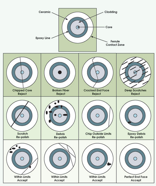
Acceptable limits for connector end-face finishing are defined as no visible defects in core or cladding, no imperfections in the ferrule contact zone and/or no contamination in the epoxy line.
Most of all, a contamination-free environment is essential to optimizing connector polishing. Five essential cleaning tools include deionized/filtered water, isopropyl alcohol, canned air, and lint-free tissues and swabs.
Clean water is needed because tap water and water from other sources can contain particles as large as 15 μm that could destroy a polished connector. To eliminate cross contamination between processing steps, alcohol should be used to clean the polishing films, connectors and the surrounding area (inside the automatic polisher) before and after each polishing cycle.
Reference meters and couplers also should be cleaned. Measuring instruments and coupling devices are the most frequently overlooked pieces of equipment for limiting cross contamination. Canned air is useful for removing debris from connector couplers and dust from connectors, films and the workstation. Even the type of lubrication can reduce return loss by as much as 5 dB in the fiber assembly.
Here to stay
Fiber optic connectors have come a long way from the days of flat end faces, high loss and extreme backreflection. With the increase in applications for fiber optic cable assemblies, the need to push performance to the limit is pressing. Do more with less for less? It’s the world we live in.
Polishing may be an old art form, but for the immediate future, it’s here to stay. Inspection criteria will undoubtedly increase, polishing procedures will be forced to change, and new connector styles will make us continuously strive to reinvent our approach to polishing.
Meet the author
Robert Rubin is an applications specialist for Ultra Tec Mfg. Inc. in Santa Ana, Calif.