Thomas Bender, Schott North America Inc.
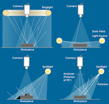
In machine vision applications, lighting strategies based on the use of fiber optics can range from directional-front to diffuse-axial, coaxial, backlit, polarized-front, ring-bright-field and ring-dark-field illumination (see figure). Compared with other options, the fiber optic method has clear strengths and weaknesses.
Lighting strategies based on optical fiber compete with other sources, such as LEDs and fluorescent lamps, in a variety of illumination schemes. The determining factor persuading the end user to choose fiber optics is usually the application’s need for high-intensity, uniform lighting.
When considering fiber optic lighting, the two most significant benefits are the potential intensity and uniformity of available light. Uniformity comes from features such as randomization, which can help eliminate irregular hot and cold spots in lamps. Light delivered to the target is also more intense than with other options — such as the direct use of LEDs and fluorescent lamps — because of the wide variety of available light sources (tungsten-halogen, metal halide, strobes, etc.) and the efficiency of fiber optic devices.
In essence, the more uniform and intense the light output, the higher the attainable processing speeds, especially with line-scan cameras. Typical machine vision uses for this type of system include high-speed web processing, which utilizes line converters for detecting flaws in large sheets, such as paper, fabric and currency. In these cases, optical fiber offers the best way to direct the maximum amount of light at the source.
Typical area-scan applications that can benefit from high light intensity and uniformity include inspection of small, extremely detailed parts, such as needles, engine components, text or markings, as well as high-magnification applications.
The use of fiber optics also offers greater beam-delivery flexibility than is possible with other illumination schemes, in part because lightguides and similar devices can be constructed in a wide variety of shapes and sizes to match the demands of specific applications. For instance, optical fiber can be placed in hazardous and industrial environments where the direct use of electronic devices might be unsafe. An example would be a paper mill, where there is a large concentration of dust in the air, and sparks could cause an explosion or a fire. By using optical fiber, the electronics could be located in a safe area, with only the fiber in the processing environment.
When used with a tungsten-halogen source, fiber provides access to full-spectrum light. In color applications, end users can couple the fiber to a light source that emits truly “white” light, yielding the best color rendition. LEDs and fluorescent sources may appear white to the human eye, but they have spectral spikes that may affect a camera’s ability to detect true color.
Even with such benefits, fiber optic illumination has some obvious weaknesses. Devices can still be more expensive than LEDs or fluorescent sources, with cost attributed mostly to the relatively high amount of labor involved in construction. Lifetime also is an issue because the tungsten-halogen lamps typically used with optical fiber have a comparatively shorter life than the other options. However, the introduction of longer-life lamps, such as metal halide, is reducing this gap.
Ultimately, the parameters to be inspected could dictate an illumination strategy that uses multiple lighting schemes. A fiber optic lightguide or other device might be required in one stage of the inspection process to monitor certain characteristics that call for intense lighting, while other light sources such as LEDs would suffice at another stage where the parameter being inspected might not require the same degree of detail.
The problem is that the most cost-effective time to incorporate such a strategy is early in the design process of the inspection task. Many users of machine vision systems either do not recognize the true impact of the illumination methodology when devising a machine vision application, or assume that lighting decisions can be put off until later. Basic considerations that do not get enough attention up front could be mechanical; e.g., how the lighting will fit into a system. The fact is, requirements for illumination are often difficult to define, and project costs can rise if adequate testing of the lighting is not performed as early as possible.
Meet the author
Thomas A. Bender is the engineering manager for the fiber optics division of Schott North America Inc. in Auburn, N.Y.; e-mail: [email protected].