Turbulent air currents may cause pressure changes in the field of machine vision. Laminar airflow and thermal management can help.
TIMO ECKHARD, CHROMASENS GMBH
It is well known from astronomical imaging that numerous atmospheric conditions and weather effects have an impact on image quality. This is caused by local changes in the refractive index of the air in the optical path. These changes are wavelength-dependent and vary with changes in the atmospheric pressure and humidity.
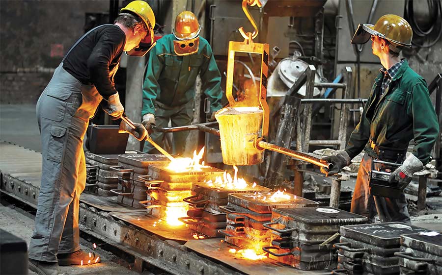
Common heat sources in manufacturing facilities that incorporate machine vision systems include illumination, high-load electronics, and high-temperature samples such as poured metal. Turbulent air currents result, often causing image warping
In the field of machine vision, both pressure and humidity can usually be assumed to be constant over the entire optical path. However, there is an exception to this rule if there are turbulent air currents in the optical path that cause local pressure changes. A typical cause of turbulences is heat convection between parts at different temperatures. Common heat sources in machine vision are the illumination, high-load electronics, and high-temperature samples such as poured metal.
Imaging with line-scan cameras
The various refractive indices in the turbulent air act as a gradient lens that warps the image content in the affected areas. The magnitude and extension of the warping is both too complex and too dependent on the setup to model mathematically. Instead, we show an example measurement of this effect to represent its typical magnitude.
Illumination technology today is migrating from traditional lights, such as halogen or fluorescence bulb lamps, to LED-based systems.
In a line-scan camera, the optical distortion is constant for each line along the scanning direction and is therefore not visible in the image. This reduces the problem to one spatial dimension, which is perpendicular to the scan direction, and the time dimension. Both dimensions can be observed at once by acquiring an image of a static target with the line-scan camera. The optical distortion will shift the position of the image content in X direction, while the extension of the warping in Y direction
represents the time information.
This shift can easily be measured by imaging a static line pattern. The basic principle of this measurement is in Figure 1. A reference image intensity profile is taken by averaging a region of interest containing an area of a few columns around each X position (depicted in green). A square test block (depicted in red) is passed along the whole column, and for each position the test data is shifted in subpixel steps via interpolation. The shift with the highest correlation between test and reference is recorded for each pixel and can be plotted in a color scale image to visualize the data.
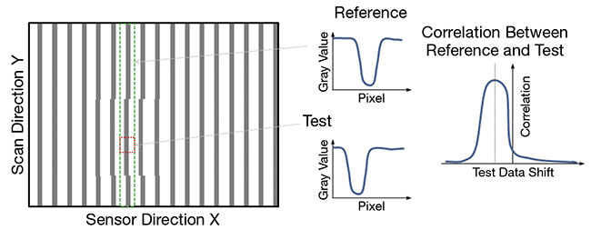
Figure 1. Sketch of the measuring scheme for the image shift. Courtesy of Chromasens GmbH.
Figure 2 shows this visualization from a static line-pattern image captured with a line-scan camera with 5-μm optical resolution. The heat source in this case is tubelight illumination that was operated at maximum LED current. In this setup, the magnitude of the optical distortion is in the range of <0.15 pixel. The turbulences are visible in the shift image as areas of similar distortion. They extend over a size of 10 to 30 mm
and persist for 200 to 800 ms.
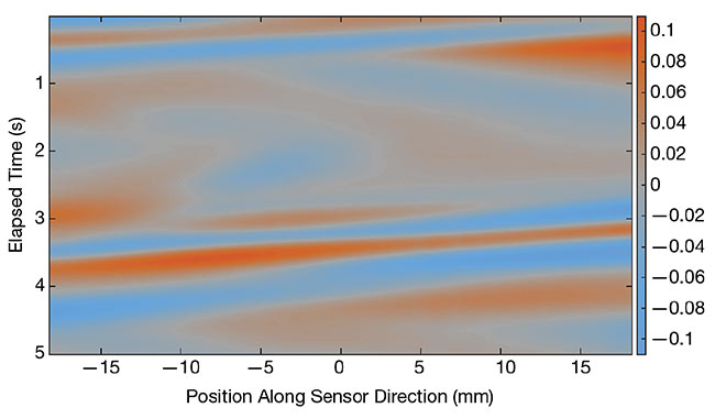
Figure 2. Color image representation of the
measured image shift. The color scale indicates
the shift in subpixel units. Courtesy of Chromasens GmbH.
This measurement shows that the magnitude of the image disturbance caused by heat convection from a standard illumination will not have a noticeable impact for standard inspec-
tion tasks. However, specialized image
processing tasks that depend on subpixel accuracy (e.g., subpixel-accurate feature extraction or subpixel-based image correlation) will likely show decreased measurement accuracy because of these distortions.
Suppression of image warping
The image warping effect can be suppressed by preventing the turbulences. For this purpose, a fan can be used to create a laminar airflow. The pressure in a laminar flow is constant, so no gradient lens effects will occur. The airflow needs to cover either the whole surface of the heat source or the whole volume of the optical path where turbulences are likely to appear.
The second option is typically easier to realize for line-scan cameras, as the optical path is constrained to a plane. The fan can therefore be installed to
the side of the camera with the flow direction along the sensor line. The air
in the volume directly below the viewing
slit of the tubelight needs to be perfused by a laminar flow. The sidewalls of the illumination block direct side access for the airstream, so the fan was installed on top of the tubelight to blow into the viewing slit at a tilted angle, as shown in Figure 3. This method reduced the magnitude of the distortion to an indiscernible size.
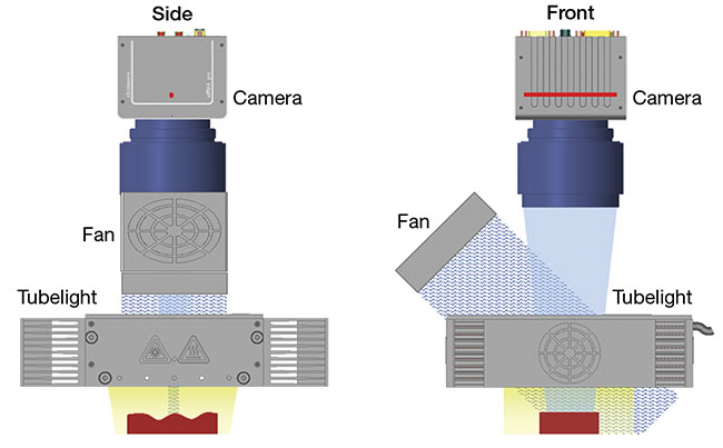
Figure 3. Side and front views of a recommended
suppression setup for a Chromasens tubelight setup. Sensor is depicted as a red point (side view) and as a red line (front view). Courtesy of Chromasens GmbH.
A heat source near the optical path can introduce image warping that
locally shifts the position of the image content. For line-scan cameras, image regions of similar shift cover several millimeters of the field of view that emerge and vanish in the time frame of about one second. Subpixel analysis of image content will be influenced negatively by this shift. To suppress this effect, it is recommended to use a laminar air current from a fan to cover the whole volume along the optical path that is affected by turbulences.
Lighting choices
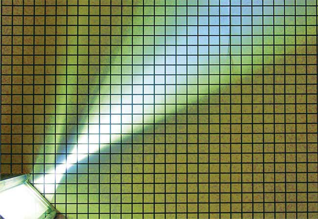
Figure 4. Light sources can generate
significant heat, as seen from a Chromasens CORONA illuminator. Courtesy of Chromasens GmbH.
Illumination choice is the first step that directly affects the quality of images acquired by line-scan cameras (Figure 4). In general, what is not illuminated correctly cannot be evaluated by soft-ware or even by humans. The effort in making the right selection is often underestimated and leads to avoidable difficulties that can increase the costs of a project, or even worse, cause it to fail. Metallic shiny, matte dark, or even transparent surfaces with different features require various types of illumination. Many aspects affect the choice of the correct illumination and have to be allowed for. These include:
- The area to be illuminated.
- The camera used.
- The speed of the application and
the camera itself.
- The color of the illuminated
objects.
- The environment.
- The behavior and characteristics of
the object (i.e., glossy or diffuse, or
varying in height).
- The expected or required lifetime
of the application.
Illumination technology today is migrating from traditional lights, such as halogen or fluorescence bulb lamps, to LED-based systems. Traditional light sources change spectrally and take longer than LEDs to reach a stable state. Additionally, these sources have a very limited lifetime. In contrast, the spectral behavior of LEDs is stable when the temperature and current are held constant. Another advantage is that LED light sources are ready for
operation almost immediately without
needing warm-up time.
Recent improvements in the stability of LEDs enable a lifetime up to 50,000 hours or more and a constant quality of spectral behavior. Lifetime is increased by adequate thermal management and also by controlling the operation mode of LED illumination. This means that if LED illumination is strobed, which is technically easy to implement, the lifetime will increase. With strobing technology, it is partially possible to use the LEDs over the maximum current for tasks where intense light is required.
What about LED heat buildup? Is LED light really a cool light source?
The fact is, when LEDs are driven hard, they burn out and die within seconds if there is not adequate cooling.
In applications where precise color reproduction is essential, cooling is strongly recommended to guarantee the thermal management of the illumination. Active thermal control systems can
control the LED’s temperature by intelligent cooling in a narrow range of <2°.
In general, the following cooling options are available:
- Passive cooling by heat sink.
- Compressed air cooling.
- Liquid cooling.
- Fan cooling.
- Temperature-controlled fan cooling.
Active airflow, compressed air, and water cooling are best for measurement applications in high-temperature environments. By monitoring the temperature of the LEDs and using a fan to control the cooling, ΔE (delta error) issues can be avoided (delta being the measure of change in visual perception of two given colors). Cooling helps to minimize the color shift of the LEDs and leads to more accurate measurements. As mentioned, it also helps to increase the lifetime of the light. LEDs are available in IR and various colors, such as red, green, blue, yellow, amber, and white. UV LEDs are also available, but with wavelengths smaller than 365 nm, the lifetime is very short and emissions are weak. However, IR-LEDs with wavelengths greater than 950 nm have a very limited output. Nevertheless, different colors and wavelengths help to make things visible on surfaces with varying spectral behaviors.
In the past, red illumination was often used where high intensities were required. However, the latest performance boosts in LED are mainly in white LEDs, as seen in the headlights
of cars or even in street lamps. The core of a white LED is in fact a blue LED. And it is the phosphors that convert part of the blue to the remaining visible spectrum.
Figure 5 shows the blue peak near 440 nm of the blue LED inside a white
LED. The remaining part of the spectrum results from the conversion material (phosphors). Technology-wise, it is a challenge for LED manufacturers to keep the color of white LEDs stable. There are tolerances in the blue chip and additional tolerances in the con-
version material. This all leads to various unwanted white colors produced within the same production line. Because of this, LED manufacturers classify LEDs into different groups. Each group (or binning) has a certain tolerance range with respect to efficiency and color. In terms of selecting the right illumination source, the binning should be considered. If the illumination modules differ in color from piece to piece, or even inside the same illumination unit, it will complicate the image analysis.
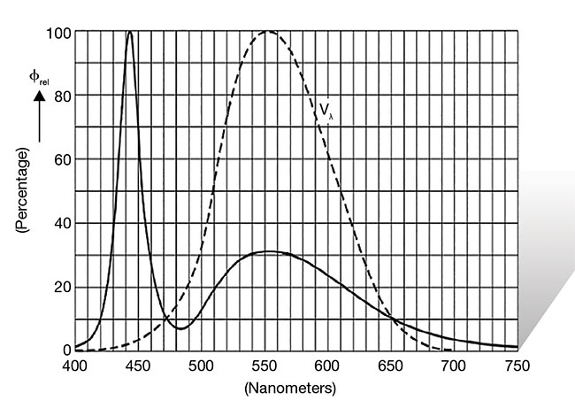
Figure 5. The core of a
white LED is a blue LED. The graph depicts the blue peak near 440 nm of the blue LED within the white. Courtesy of Chromasens GmbH.
Another type of LED is the UV LED, which is used to make fluorescence marks visible. In many cases, 405-nm light sources are sufficient to excite fluorescent substances. However, for
curing processes of glue, varnish, or
resin, UV LEDs may be the better choice. UV LEDs are not as powerful,
compared to blue/white LEDs, but their
intensity can be increased by focusing the UV beams via reflector technology.
IR lights are commonly used in food inspection applications to detect organic materials. Wavelengths of 1200 to
1700 nm can help to distinguish between different materials. Unfortunately,
today’s IR LEDs in these wavelength
ranges are not yet powerful enough, so
conventional halogen bulbs with filters
are used.
Finally, a word on LED controllers. If the LED controller is not stable in terms
of temperature variations or supply cur-
rent to the LEDs, brightness changes can make material inspection impossible. This is especially true with the very
high frequencies of line-scan cameras. Short-term fluctuations in brightness
will immediately be visible.
Meet the author
Timo Eckhard is a team leader for
research and innovation, innovation
and IP management at Chromasens GmbH, which develops and fabricates high-end industrial camera systems, light sources, and corresponding software solutions. Eckhard received a doctorate from the University of Granada (UGR) in 2015. In 2011, he received Master of Science degrees from Université Jean Monnet (France), the University of Eastern Finland (Finland), Gjøvik University College (Norway), and UGR (Spain). His current research interests are in the fields of optical imaging system design, image processing and analysis, optical 3D measurement, and spectral and multispectral imaging.