
Fluorescence Lifetime Imaging – Application Simplified…
Gerhard Holst
For many years the phenomenon of photoluminescence has been used for a variety of purposes in
life science applications, ranging from bio markers to sensing actions. Each of the luminophores that
are applied has multiple characteristic parameters, which can be exploited for investigations. The
most prominent parameter is the luminescent emission itself, the fluorescence or phosphorescence
intensity. The intensity is used qualitatively and quantitatively, but the latter strongly depends on the
light field and the optical conditions around the luminophore. Similarly it is known that the
luminescence decay or lifetime is an additional characteristic parameter of such a dye, which can
provide additional information (see figure 1) or more reliable information than the luminescence
intensity.
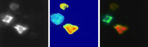
Figure 1: Three cells labelled with FRET pairs: the left image shows the donor fluorescence, which does not indicate
whether FRET has occurred or not. The middle image shows the donor fluorescence lifetime distribution as
measured with the pco.flim camera system in the frequency domain. The right image shows the
fluorescence lifetime distribution of the middle image, but weighted with the fluorescence intensity of the
left image, which clearly shows the cell which has undergone a FRET process, because it has a shorter
lifetime (blue-green coded) than the others.
Although the possibilities of the luminescence lifetime have been known for many years, only few
commercial camera systems are available. There are image intensifier based camera systems for
frequency domain FLIM or scanning systems for time domain FLIM and camera based systems for
time domain FLIM for longer lifetimes (range of microseconds and longer). Additional equipment
such as frequency or timing generators was required to create such systems, which in many cases
were quite bulky and expensive.
Due to technical developments in the area of CMOS image sensors, it is now possible to manufacture
image sensors whose pixels can be directly modulated up to 50 MHz, which is an excellent
prerequisite for the design of an all solid-state frequency domain FLIM camera system. Based on such
a new CMOS image sensor, a highly integrated frequency domain FLIM camera system has been
developed, which reduces efforts and costs of luminescence lifetime imaging systems. The principle
is based on a charge swing in each pixel which allows for a very fast change of the direction of the
luminescence induced charge carriers. In case of the pco.flim camera system it allows for modulation
frequencies of up to 50 MHz. If a luminophore is excited by a sinusoidally modulated light it will react
with a sinusoidal emission of light, but the reaction will be delayed due to the luminescence lifetime.
This delay, technically called a phase angle between the excitation and emission, can be measured.
Figure 2 shows the charge swing of the pixel, how it synchronizes with the integration of half the
sinus signal and how it can be used to measure the phase angle of the emission.
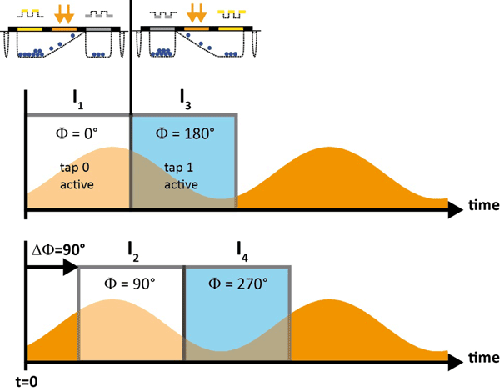
Figure 2: Sinusoidal luminescence signal (orange) with sampling integration windows (grey rectangles). First, for the
first half of the period, the image I1 is integrated, which means that tap 0 is active and Φ = 0°, and
subsequently the image I3 is integrated, which means that tap 1 is active and Φ = 180°. For the next
recording the synchronization is shifted by ΔΦ= 90°, so that the first half period of integration covers I2,
which means that tap 0 is active and Φ = 90°, and subsequently the image I4 is integrated, which means that
tap 1 is active and Φ = 270°.
While the switch in the pixel points to tap 0, all generated charge carriers are collected there; this is
done to integrate along half of the period of the sinusoidal emission, then the switch changes
direction, and the second half period is integrated into tap 1. The first integral corresponds to the
phase angle value of 0° (tap 0) and the second integral corresponds to a phase angle value of 180°
(tap 1). To reconstruct the sinus signal and determine the phase angle at minimum, a second
measurement is required. Therefore a phase angle offset of 90° is introduced between the excitation
and the emission, and the measurement is repeated (lower signal in figure 2). Now the integrals
correspond to the phase angles of 90° (tap 0) and 270° (tap1). With these values or images it is
possible to calculate three images: an image of the luminescence intensity, an image of the phase
angle distribution and an image of the modulation index distribution. The latter two can be
converted into luminescence lifetime distributions. Since one integration in most cases is not
enough, the integration is repeated until sufficient signal is collected, which means that during an
exposure time of for example 10 ms, the switch is triggered with the modulation frequency.
FLIM set-up
Now the devices needed for a FLIM measurement are the new pco.flim camera system and an
appropriate light source that can use the modulation signals and the dark gate signal coming from
the camera. In principle, that is all that is needed. Figure 3 shows a structural overview of a set-up for luminescence lifetime imaging with a pco.flim camera system, in which the camera is the frequency master. The pco.flim camera sends the modulation signal and the “dark” gate signal to the light source, which should be capable of accepting both signals. While the modulation signal controls the
modulation of the excitation light, the gate signal controls whether the excitation light in general is
switched ON or OFF, because the light has to be switched OFF during image readout time1.
It depends on the application which modulatable light source (fig. 3, modulatable light source) is
appropriate (the required frequency range), which can be anything from LED to laser diodes that can
be properly modulated in the intended frequency range. The modulated light can pass an optical
excitation light filter (fig. 3, excitation filter) and will excite the luminophore in the sample of interest.
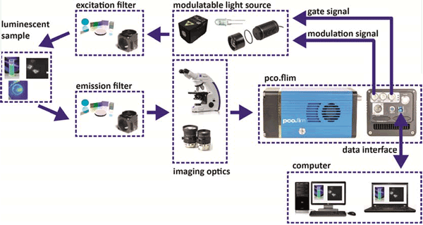
Figure 3: Structural overview of a set-up for luminescence lifetime imaging with a pco.flim camera system.
For that purpose it might be necessary to add additional optics to guide and shape the light to the
sample. The optics are not included in the overview. The luminescent sample in turn will emit
luminescence light. This light has to pass some sort of optical emission filters (fig. 3, emission filter)
and will be imaged by optics (fig. 3, imaging optics) to the image sensor of the pco.flim. It is not
important whether the emission has to first pass the optics and then the filter or vice versa; figure 3
shows just one version. The optics can range from lenses to microscopes, depending on the
application. According to the operation modes and settings, the pco.flim camera system will transfer
the images to the controlling computer (fig. 3, computer) via the USB 3.0 data interface. The
examples given in figure 3 are just placeholders to show the flexibility of the pco.flim system. Since
the camera includes the generation and control of the modulation signals, the overall set-up is
reasonably simple.
Frequency vs. time domain luminescence lifetime measurements
In theory there is no difference regarding the information content of the two types of decay or
lifetime measurements, since both methods give the same results, but with different experimental
requirements. The frequency domain measurement requires a reference measurement to cancel out
the influence of the optical path, which might not be necessary for the time domain measurement, but time domain measurements with image sensors are not possible down to the nanosecond range,since the fastest available CMOS image sensors still have minimum exposure times of more than 100
nanoseconds, while the frequency domain camera system pco.flim, even at a modulation frequency
of 30 MHz (which is below the optimum frequency of 160 MHz), can resolve 100 picosesconds. For
example the differences between the blue and the red cell in figure 1 (middle) were in the range of
1.5 ns.
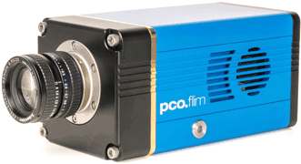
Figure 4: The pco.flim FLIM camera system.
FLIM camera system
The FLIM camera system pco.flim includes a complete frequency synthesizer, which is required for
the generation of the modulation signals in the frequency domain. Therefore the only further device
needed for FLIM measurements is an appropriate excitation light source, which can use either
sinusoidal or rectangular modulation signals and a dark gate signal to switch off the light during
readout of an image. The pco.flim has a resolution of 1008 x 1008 pixels and can read out a
maximum of 80 double images/s. The effective frame rate is about 20 frames/s, due to the fact that a
minimum of 2 double images have to be read out for a proper sinus fit and this has to be done twice
for a proper asymmetry correction. The camera system can be operated at a single frequency or
multiple frequencies in the range of 5 kHz – 50 MHz and it can perform an asymmetry correction
even before image readout. With its widely used USB 3.0 interface it can connect to all sorts of
computers. A thermo-electrical Peltier cooler keeps the image sensor at 10 °C by using either a fan or
a water cooler to dissipate its own waste heat. With the c-mount it is easy to connect to any
microscope or lens. Therefore the camera system significantly reduces the required efforts and costs
for operation and research.
Application simplified
If it is integrated into a good software environment, the measurement of 2D fluorescence lifetime
distributions now has been simplified. Instead of an image intensifier camera, light source and timing or frequency generators, the application requires only a CMOS camera and light source, which should enable a broad range of applications that were previously unfeasible due to the complexity of the existing system requirements.
Therefore, numerous applications, including FRET applications for measuring the donor fluorescence
to determine how much FRET has occurred, the measurement of auto fluorescence lifetimes in
natural tissue or the measurement of the luminescence lifetime for sensing purposes ranging from
optical chemical sensors on a cellular scale up to the use of pressure sensitive paint in wind tunnels, can all benefit from the new FLIM system.
1 The QMFLIM2 Image Sensor catches additional noise, when the light is on during the readout of the Image sensor.
/Buyers_Guide/PCO-TECH_Inc/c11454