Thermal effects in lenses and windows can have a dramatic effect on industrial applications.
Felix Abt, Axel Heß and Friedrich Dausinger, FGSW Forschungsgesellschaft für Strahlwerkzeuge mbH
New generations of thin-disk and fiber lasers are combining excellent beam quality — M2 typically between 1.2 and ∼8 — with kilowatts output power. This combination brings the performance of beam-forming optics into question.1, 2 In this article, we will discuss the emerging difficulties of focusing these high-brightness laser beams for materials-processing applications.
Appropriate power density and distribution in the focal plane are key factors for efficient and reliable materials processing. To achieve this, the laser beam must be transformed by an optical system. Such systems normally are composed of a collimation unit and a focusing unit (Figure 1).
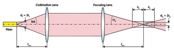
Figure 1. The typical optical system in a high-power industrial laser system includes collimation and focusing optics. The focal length of the collimation and focusing lenses are fcol and ffoc, respectively; NA is the numerical aperture of the delivery fiber; and zR is the Rayleigh distance.
The focal diameter depends on the divergence angle and on the beam-parameter product (bpp) of the focused beam.
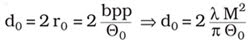
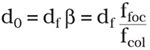
Alternatively, the optical magnification (β) — the quotient of the focal length of the focusing lens divided by that of the collimation lens — can be used to calculate the focal diameter. The focal diameter on the workpiece thereby is given by the product of optical magnification and the core diameter of the transport fiber.
When using high-quality laser beams (near the diffraction limit), degradation of the beam quality resulting from deficient optical components becomes an important issue.
Measurement setup
Our measurements with a 1-kW single-mode fiber laser (M2 = 1.2, as measured at the output transport fiber) have revealed some interesting potential problems for industrial applications with such lasers. We measured the beam quality, the focal diameter and the longitudinal position of the focused spot with the camera-based MicroSpotMonitor from Primes GmbH of Pfungstadt, Germany. The device is equipped with exchangeable measurement objectives and internal beam attenuation for measurement of multikilowatt laser beams with focal diameters down to 1 μm. A detailed explanation of the measuring method on which it is based is provided in References 2 and 3. The instrument can measure the whole beam caustic with all relevant values that characterize the laser beam, according to ISO 11146.
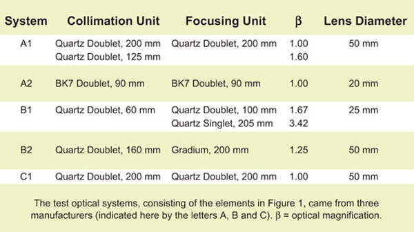
In our experiments, we tested optical systems — with lens diameters from 20 to 50 mm — from three manufacturers. With various combinations of focusing and collimating units, we achieved optical magnifications of 1.0 to 3.42. All tested configurations are listed in the table.
Distortions
Our measurements show that imperfections in the lenses and intermediate optics, such as beamsplitters or protective windows, can degrade the beam quality significantly from the value measured at the output of the laser. This degradation is more critical for beams with a very low M2 than for classical multimode beams. For diffraction-limited beams, even very small disturbances and thermal effects can cause dramatic changes in quality and in the focal diameter at the workpiece.
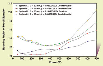
Figure 2. The blooming (quotient of measured and calculated focal diameter) of the resulting focal diameter is dependent on the laser power and the involved optics. D = lens diameter; β = optical magnification.
We measured beam quality and focal position at laser powers between 50 and 900 W. From our measurements, two facts become obvious. First, in most cases, the transmission quality of an optical system is not diffraction-limited; second, transmission quality is dependent on the thermal load of the system, which is induced by absorbed laser power.
From the measurements of the beam quality emerging from the delivery fiber, we calculated the “blooming” of the focused spot on the workpiece as a function of power for the various systems (Figure 2). As these curves show, distortion from the optical focusing and delivery system can result in a focused spot that is twice as big as expected or can produce a spot with as little as one-quarter the expected power density. So one must realize that the classic model to calculate the focal diameter (Equation 2) is not working in most cases for diffraction-limited high-power lasers.
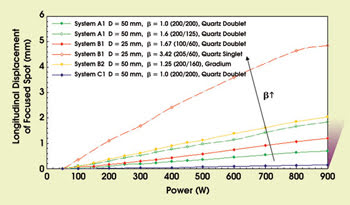
Figure 3. The laser-induced focal shift (longitudinal displacement of the focused spot) is shown as a function of laser power. The focal shift is strongly dependent on magnification. D = lens diameter; β = optical magnification.
Distortions in the beam delivery optics not only enlarge the focused spot size but also can translate it longitudinally. This laser-induced shift is caused by the absorption of laser light, which results in rising local temperatures of the involved lenses and of the intermediate optics. The temperature gradient results in mechanical deformation and a radial gradient of the refraction index (that is, thermal lensing). Both effects lead to a reduction of the effective focal length of the system. This process is strongly dependent on the power density of the laser beam and on the cooling of the optical components.
The fact that the power in a Gaussian beam is concentrated in its center — unlike in a top-hat beam — only increases the problem. Additionally, the focal shift is dependent on the magnification of the optical system.1 These considerations make it difficult to find the right setup for materials processing at varying laser power.
We measured the longitudinal shift in the position of the focused spot to be as large as 5 mm with our experimental systems (Figure 3). The data show that the shift is strongly dependent on the magnification of the beam delivery system.
Based on the lens equation, it can be shown that the laser-induced focal shift is quadratically dependent on the optical magnification1:
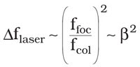
where Δflaser is the laser-induced focal shift or the longitudinal displacement of the focused spot from its nominal position.
Thus, the focal shift of a focusing unit with an optical magnification of 2.0 is about four times higher than that of a focusing unit with a magnification of 1.0. As an example from Figure 3, System B1 has a focal shift of 1.4 μm/W for β = 1.67 and 5.7 μm/W for β = 3.42. This mathematical relationship makes the comparison of optical systems difficult.
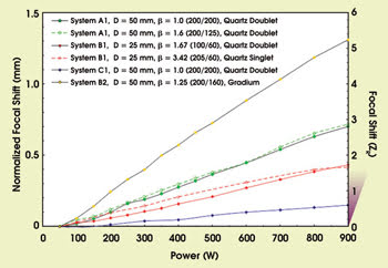
Figure 4. This chart shows the normalized focal shift (Δfnormalized) as a function of laser power. The right axis shows the normalized focal shift in terms of the beams’ Rayleigh lengths. There is negligible focal shift for powers less than 50 W. D = lens diameter; β = optical magnification.
But this issue is not as critical for materials processing as it appears because both the longitudinal shift, Δflaser, and the depth of focus vary quadratically with the magnification. In other words, greater magnification results in greater longitudinal shift, but it also means that the beam is focused less sharply, so a given longitudinal shift produces less change in spot size and, therefore, in power density.
Focal shifts
Mathematically, the quotient between the Rayleigh length and the longitudinal shift is the relevant factor. The Rayleigh length is the distance from the beam waist to where the beam has grown larger than the waist by a factor of √2; that is, it is a measure of how sharply the beam is focused, or of the depth of focus (see Figure 1). Therefore, if the beam waist is shifted by one Rayleigh length, the power density is only one-half of the power density in the beam waist.
With this knowledge, we can normalize the measured focal shift with the optical magnification:
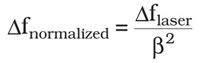
This leads to a representation of the focal shift, where optical systems with various magnifications can be benchmarked and directly compared with each other (Figure 4). This means that, if two optics with different optical magnification have the same normalized focal shift, the effect on the power density is the same. The two tested configurations of system A1, for example, have the same normalized focal shift independent of their optical magnification (β = 1.0 or 1.6), and, hence, the effect on the power density is the same for both configurations. Consequently, it is unimportant which optical magnifications you use.
Power density
Figure 5 illustrates this circumstance for two different focusing lenses. Both configurations are illuminated with the same laser power. The measured focal shifts are different (0.25 mm versus 0.563 mm), but what does this mean for the power density on the workpiece? Both configurations shifted by one Rayleigh length, resulting in a halved power density for both configurations. Furthermore, we can normalize the measured focal shift by dividing it by the square of the optical magnification. This results in a normalized shift of 0.25 mm for both configurations.
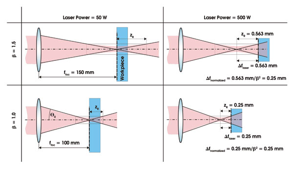
Figure 5. This comparison between optical systems with two different optical magnifications illustrates the concept explained in the text. The situation on the left is at low laser power, while the situation on the right is at high laser power. The measured longitudinal shift of the focused spot is different for the two systems, but the effect on the power density at the workpiece is the same.
The data shown in Figure 4 are independent of the optical magnification, so the significant differences between the optical concepts of the different manufacturers can be shown. For the tested optics, the measured focal shift was between 0.7 and 6.1 zR/kW, where zR is the Rayleigh distance.
Another important thing to know is that glass windows can influence the focal shift of an optical head as well as the achievable focal diameter. For one configuration, we tested the influence of three windows: a new one made of fused silica, one new one made of BK7 and a used one, also made of BK7. Figure 6 shows their effect on the focused spot size and its longitudinal shift.
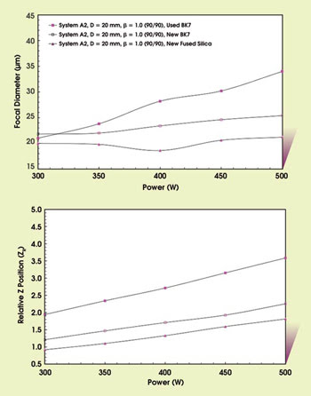
Figure 6. Using three different glass windows resulted in measurable differences in the focused spot diameter (top) and in the longitudinal displacement (bottom).
It is obvious that the fused-silica glass provided the best results in laser-induced focal shift as well as in the achieved focal diameter. The new BK7 is slightly worse than the fused silica but still provides acceptable focal diameter and not too large a dependency on the laser power.
But if we have a closer look at the results with the used BK7 window, we see that the focal shift is twice that of the fused silica (0.9 mm/kW versus 1.8 mm/kW), and the blooming of the focused spot also is significantly greater. Additionally, the focal diameter is sharply dependent on the laser power, making it difficult to process with different power levels.
A troubling observation is that the used BK7 window has no contamination that is visible to the eye. Thus, the standard visual inspection of the optical components is not sufficient to ensure stable conditions for materials processing.
The two effects we have been discussing here — distortion resulting from thermal absorption in lenses and in windows — can lead to serious problems in finding the appropriate setup for a specific application. In many materials-processing systems, it is commonplace to measure the beam parameters at low laser power; that is, when the effects we have been discussing are not present. As we have shown, the true parameters can be significantly different at high power. Hence, we strongly recommend evaluating an optical system before integrating it into industrial processes. Furthermore, continuous monitoring of the focused laser beam and of the optical system is a key factor for reliable processes with high-power single-mode lasers.
Meet the authors
Felix Abt is a mechatronics engineer, Axel Heß is a mechanical engineer, and Friedrich Dausinger is chief scientist, all at FGSW Forschungsgesellschaft für Strahlwerkzeuge mbH in Stuttgart, Germany; e-mail: [email protected].
References
1. B. Wedel and R. Niedrig (2006). Anforderungen an die Laserbearbeitungsköpfe beim Schweißen mit hoher Strahlqualität, 5. Laser-Anwenderforum, Bremen, Germany.
2. O. Märten et al (2007). Determination of thermal focus drift with high power disk and fiber lasers, Proc. 4th International WLT-Conference on Lasers in Manufacturing, Munich, Germany.
3. Primes GmbH (2007). Users’ Manual and Documentation: Primes MicroSpotMonitor. LaserDiagnoseSoftware 2.8.1, Pfungstadt, Germany.