A cohesive workflow and precision 3D printing have allowed for adapting multiple elements in manufacturing.
Matthias Beier and Johannes Hartung, Fraunhofer Institute for Applied Optics and Precision Engineering IOF
Metal optics have been around for a long time in a variety of industrial and commercial applications. Recently, new options have been added to freeform optics in the manufacturing process. With new materials, improved precision machining, and the opportunity presented by the use of 3D printing, metal optics technology has enabled innovative design approaches using big data analysis.
Precision polishing by magnetorheological finishing. Courtesy of Reference 2.
The result is a new generation of lightweight and highly integrated optics at use in the aeronautics and laser technology sectors. Two or more mirrors and reference elements can be machined in one piece. Bionic substrate designs, with innovative lightweight concepts or integrated cooling channels, become available. Such systems may serve in satellite missions, as well as in high-power materials processing. Scientists at the Fraunhofer Institute for Applied Optics and Precision Engineering IOF in Jena, Germany, developed a process chain to bring this integrated freeform optics technology from the lab to the shop floor (Figure 1, next page), and they founded a startup called SPACEOPTIX GmbH to commercialize the effort.
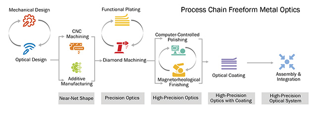
Figure 1. The workflow for the processing of high-precision metal optics. Courtesy of Fraunhofer IOF.
Optical design considerations
Freeform optics can correct for asymmetric optical aberrations. The devices allow for the shrinkage of the technology itself, or even the reduction of the number of required optical elements. As a result, complexity and, in most cases, the costs of production are reduced. But a number of special design considerations are also required.
For example, by introducing asymmetric features on a mirror surface, a turning operation with three linear and one rotational axis becomes necessary (Figure 2). Coordinate transformations from the design program to the machine coordinates have to be considered accordingly. The same applies to all polishing processes.
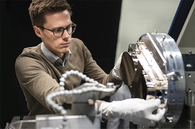
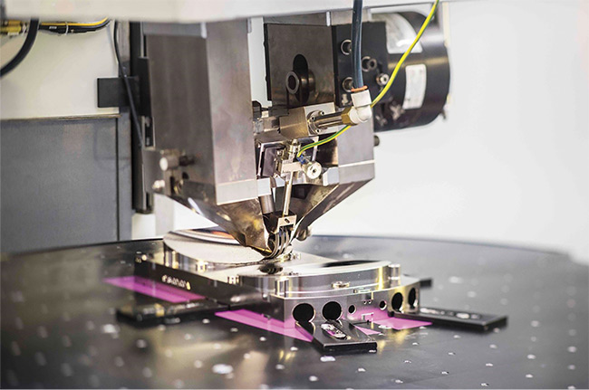
Figure 2. Diamond turning of several components on one substrate allows for precision limited only by that of the tool. Courtesy of Fraunhofer IOF.
The situation becomes more complex if several mirrors are to be manufactured on one substrate, because this reduces the size and cost in space applications, for instance. An additional benefit of making several optics on one substrate — in one clamping — is a reduction of alignment errors in the settings of the turning machine. But the geometry in the workspace may limit the options. If one mirror or reference is much higher than the others, it may become impossible to process the lower ones because the higher one is in the way of the lathe. The height limit is the maximum upstroke of the precision turning machine. The design approach has to be adapted accordingly.
In one approach, the mirror with the lowest z values in the manufacturing coordinates can be built directly on the substrate. The mirror with the higher z values is integrated (screwed) on the substrate after machining of the first one is completed, to account for proper placement. Both are therefore manufactured during the same clamping operation. This approach may also be beneficial for reference elements that have a distinct height in comparison to the mirrors.
A second approach assumes that all mirrors on the substrate are located on nearly the same plane and have curvatures that don’t deviate too much in relation to each other. Thus the mirrors can be processed in this setup. Now the required speed of the machine can be considered. A slow tool means low acceleration and higher stroke. Fast-tool manufacturing allows for less processing time and less stroke, and hence the asymmetry should be lower.
Other considerations for optical design can be derived from referencing and metrology. It is necessary to reserve enough space between the ray bundles and other optical surfaces to place reference elements (either tactile or the larger optical references) close to the mirror surfaces. And a certain boundary region is necessary, to reduce boundary-effect-induced degradation of the surface quality caused by the post-polishing processes.
Mechanical design considerations
A strong impetus for the development of integrated metal optics comes from applications in satellite technology. Temperature differences between production and operational environments are common in this context. It becomes particularly challenging when the optics are cooled with liquid nitrogen. Two problems arise from such thermal loads: First, dimensions change; and second, tensions between various materials come up due to different coefficients of thermal expansion (CTEs). The latter may lead to bending or peeling of the coating.
At normal temperatures, such shrinking effects could be accounted for by appropriate tolerancing. But when cooling down to the temperature of liquid nitrogen, these effects far exceed tolerable values. A precompensation of the thermal load can be a solution. The shrinking and bending can be calculated using a finite element analysis. Such analysis also allows calculating a shape of the optics that reaches its desired form just after cooling down. Obviously, this precompensation works best for a fixed end temperature.
The countermeasure to peeling of functional coatings is a proper selection of coating materials. The CTE of the coating has to be as close to that of the substrate material as possible. The scientists at Fraunhofer IOF have developed a special combination of aluminum silicon alloy for the substrate, and electroless nickel phosphorus (NiP) for the plating. After extensive material tests, the relation of 40% silica to 60% aluminum turned out to be crucial to match the CTE of the substrate and plating material.
Metal optics from a 3D printer
Additional opportunities for the use of freeform optics arise in 3D metal printing, or additive manufacturing. With this type of manufacturing, the structure of a mirror can be changed radically. For weight optimization, bionic structures or natural elements can be introduced, which retains the rigidity of a mirror while saving up to 70% of the resulting weight. At the same time, the stiffness or natural frequency of the part may be tuned. Or cooling structures may be added into the mirror substrate. Respective solutions have been developed1 and shown to be compatible with the general workflow, as shown in Figure 1.
While the optical design is not much changed, the use of additive manufacturing produces more challenges within the mechanical design process. First, the outer contour may stay the same, since only the inner structure is modified to reduce weight. This design step involves heavy data exchange between the CAD program and the mathematical software for the structure reduction. Results of the modeling process2 are shown in Figure 3. Furthermore, any fixation or reference structure that is to be produced with the additive manufacturing process must also be included in the design specifications2.
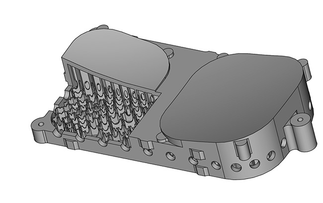
Figure 3. A double-mirror substrate with internal structures designed for additive
manufacturing techniques. Special holes in the walls of the cells are included for powder removal. Courtesy of Reference 2.
Second, the material for additive manufacturing has to be considered for thermal loads. The number of available materials is still limited due to cost, so the choice is smaller than for conventional mirrors. Furthermore, materials with matching CTEs have to be found. In a separate research project1, scientists from Fraunhofer IOF developed and tested a three-mirror anastigmatic telescope. With the newly developed combination of NiP and AlSi40 (an aluminum-silicon alloy), the CTE of the mirror substrate and plating were matched. This resulted in a minimum of bimetallic bending and led to a thermally stable design.
Precision machining
When the optical and mechanical design is completed, the actual processing starts. Either a conventional computerized numerical control (CNC) process or additive manufacturing is used to prepare the module for precision machining. The method of choice is diamond turning, and for the modules2 shown in the opening image (page E18), a Moore Nanotechnology 450 UPL was used.
A first step is again data processing. The toolpath has to be generated. For this purpose, the mirror surface data has to be decomposed into a rotational part and a freeform part. Several constraints have to be considered, depending on the type of machine. For the device2 shown in Figure 3, they are:
1. A freeform tool stroke of ≤6 mm.
2. Azimuthal gradients of ≤10° (angle of clearance ≤20°).
3. Azimuthal accelerations of ≤5 g (frequency responses allow 0:2 to 7:5 g).
A new two-dimensional algorithm has been developed by Fraunhofer IOF for this procedure. During the whole precision turning process, the shape is measured using a tactile 2.5D profilometer with a resolution of less than 50 nm peak to valley. Corrective machining approaches are used to reduce surface figure deviations coming from the cutting process.
Finishing the surfaces
A polishing toolpath for magnetorheological finishing — a precision surface-finishing technology — can be derived from the diamond turning toolpath or the overall mathematical surface description. Boundary conditions from the machine setup, such as available wheel sizes and maximum machining capacity, have to be taken into account.
Subsequent to this final polishing step, artifacts from diamond turning and magnetorheological finishing have to be measured. For this purpose, the surface is measured at various resolutions and analyzed in detail by creating a radially averaged power spectral density. This calculation is improved by using not only one measurement point, but a measurement field sampling at various resolutions, creating a full surface characterization map based on interferometric, white-light interferometric, or even atomic force microscopic data.
Finally, the information provided by this map is used to remove the remaining traces on the surface with another iteration of magnetorheological finishing and computer-controlled polishing. More surface measurements are required during this iteration. For a proper form after the polishing, it is beneficial to use an interferometric setup with a computer-generated hologram to verify the quality of the mirror surfaces.
When the polishing process is completed successfully, the module can be assembled. Based on the unified reference concept and the massive data analysis in the previous steps, it becomes possible to simplify the assembly and integration process. The techniques allow for an assembly of multifreeform systems with single-micrometer-alignment tolerances within only a few hours. This improved workflow is a substantial benefit compared to previous procedures and makes a serial production much more efficient
Metal optics prospects
Precision metal optics can be manufactured in a highly integrated way. For example, prototypes of two-mirror modules have been produced for a three-mirror anastigmatic telescope based on a new workflow can be seen in the image on the opening page. Processing of several optical elements on one substrate has been shown. This reduces the alignment effort. It can be further reduced by integrated references.
All steps, from design to assembly, are supported by a heavy data processing concept. In particular, during the mechanical design stage, a data exchange is optimized between data analysis tools, the commercial optical design programs, and their mechanical design counterparts. This concept can also integrate new methods such as additive manufacturing into the workflow for high-precision freeform optics. For substantial thermal or stable mechanical loads, a precompensation process has been established.
In the polishing stage, a toolpath continuation was improved to achieve smooth sag values in radial direction to mitigate certain acceleration artifacts. A topic of further research, when it comes to higher derivatives of the toolpath, is the improvement of post-polishing steps.
On the application side, this concept has been developed for precision optics modules. Metal optics can offer cost benefits compared to conventional glass optics. New areas of application, such as space and astronomy equipment, are obvious. But the development of 3D-printed metal optics is still in its infancy. Built-in cooling structures allow for the handling of high-power beams, whereas bionic structures (Figure 4) allow for lightweight mirrors with retained stiffness, as needed for scanner mirrors. The technology is just making its way into various markets. More applications will make use of the new opportunities.
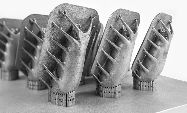
Figure 4. Bionic structures can be realized using additive manufacturing. A scanner mirror has been optimized for low deformation at high accelerations and high natural frequency. Courtesy of Fraunhofer IOF.
Meet the authors
Matthias Beier is Group Leader Ultra Precision Manufacturing/Freeform Optics in the Department Precision Engineering at the Fraunhofer Institute for Applied Optics and Precision Engineering IOF in Jena, Germany. He is co-founder of the Fraunhofer spinoff SPACEOPTIX. The startup targets a commercialization of the integrated freeform optics technology chain to address the manufacturing of high-quality metal optical components and systems for applications in space, astronomy, and industry.
Johannes Hartung is a data analysis scientist within the Ultra Precision Manufacturing/Freeform Optics group in the Precision Engineering Department at the Fraunhofer Institute for Applied Optics and Precision Engineering IOF in Jena, Germany. He has a background in theoretical physics.
References
1. E. Hilpert et al. (2018). Precision manufacturing of a lightweight mirror body made by selective laser melting. Prec Eng, Vol. 53, pp. 310-317, www.doi.org/10.1016/j.precisioneng.2018.04.013.
2. N. Heidler et al. (June 15, 2018). Additive manufacturing of metal mirrors for TMA telescope. Proc SPIE, Vol. 10692, Optical Fabrication, Testing, and Metrology VI, 106920C, www.doi.org/10.1117/12.2316343.
3. J. Hartung et al. (June 5, 2018). Novel applications based on freeform technologies. Proc SPIE, Vol. 10692, Optical Fabrication, Testing, and Metrology VI, 106920K, www.doi.org/10.1117/12.2313100.