With advancements in low-noise optical signal processing circuits and affordable, long-coherence-length lasers, frequency-modulated continuous-wave sensing is becoming a viable alternative for 3D vision systems of the future.
Ralf J. Muenster, SiLC Technologies Inc.
Supply chain disruptions during the COVID-19
pandemic have been a wake-up call for most, resulting in the acceleration of the onshoring trend started by the U.S.-China tensions. Offsetting higher wage structures with automation is key to a sustained home-based manufacturing business.
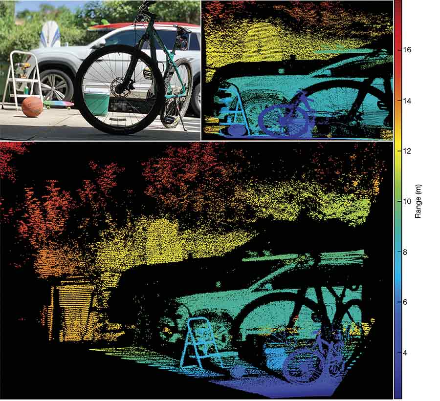
Outdoor scan using a frequency-modulated continuous-wave (FMCW) 4D vision system. Courtesy of SiLC Technologies.
Luckily, manufacturing robotics has come a long way in the last decade, in part enabled by new technologies such as 3D machine vision. While most of today’s 3D vision systems still suffer from significant trade-offs in terms of range, eye safety, crosstalk immunity, and precision, a new approach using a coherent-sensing technique provides promising relief.
Rather than relying on time of flight, stereo vision, triangulation, or structured light, frequency-modulated continuous-wave (FMCW) sensing takes advantage of the properties of photons themselves. Extensive use of this approach has been prevented in the past due to the cost and the number of components needed.
Competing 3D technologies
Similar to the human stereo vision, 3D information is extracted by comparing the images taken from two vantage points. By comparing the two images, relative depth information can be obtained in the form of a disparity map, which encodes the relative difference of corresponding image points. The values in the disparity map are inversely proportional to the scene depth at the corresponding pixel location.
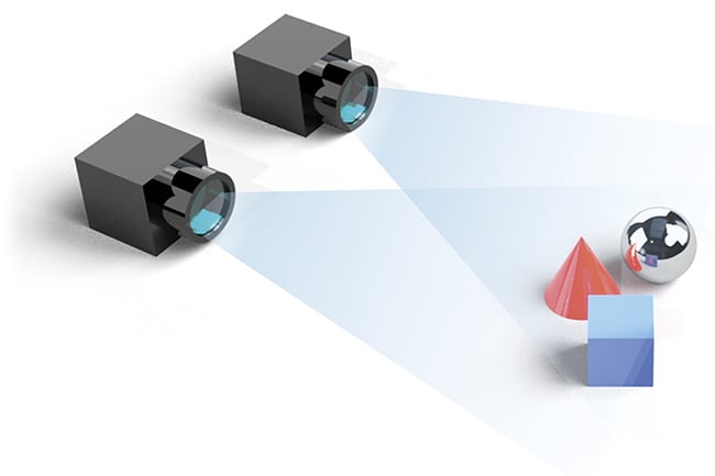
Stereo vision systems extract depth information by matching the same point in two images. Courtesy of SiLC Technologies.
For stereo vision to work, it is key to identify the corresponding pixel in each image. Either patches of pixels or distinct features and landmarks need to be matched. However, matching algorithms is not a trivial task. Depending on resolution, the computing power required can be significant. Also, image noise or illumination can get in the way. Cameras, in general, don’t work well under difficult lighting conditions, such as glare or high-dynamic-range situations. And if there is no clear structure in the images, no 3D information can be extracted.
Most importantly, the depth accuracy and resolution are dependent on the distance between the two cameras (known as the baseline). A distance of 1 m is needed to get a range error of 10 cm at 20 m with a high-end 8-MP camera1.
Unlike the passive stereo vision approach, structured-light depth sensing projects a known pattern — for example, horizontal parallel lines — onto a scene, and then captures the scene with a camera system. When the pattern hits an object that has a three-dimensional structure, the pattern deforms. From an image of the deformed pattern, vision algorithms can then calculate the depth information of the scene. The projection light source is typically a laser in the near-infrared spectrum from 850 to 940 nm.
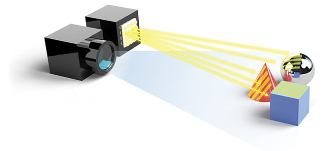
Structured light projects a pattern onto the object and uses the pattern distortion to reconstruct the object’s shape. Courtesy of SiLC Technologies.
3D structured light offers higher accuracy, but the illumination of the scene with a projected pattern limits the approach’s range and field of view. Furthermore, the choice of patterns is not always straightforward and can depend strongly on the scene. The structured-light approach captures the scene with a CMOS or CCD image sensor and, similar to the two-camera stereo system, offers a snapshot-like approach.
Laser triangulation has been around for decades, and this technology is still widely used, primarily to sense precise depth at a single point on the object. In fact, it is the underlying measurement principle for stereo vision and structured light. Triangulation uses a laser and a camera device, with the laser, camera, and measurement object defining a spatial triangle.
Within this triangle, the distance between the sensors is the base B and must be known. By determining the angles between the projection rays of the sensors, the bases, and the intersection point, the 3D coordinates are calculated from the triangular relations.
The benefits of 3D triangulation are very high resolution and accuracy, with a millimeter to micrometer resolution scalability. However, with the distance of the base B being limited in a typical application, combined with a longer measuring time, this approach is suitable only for short measuring distances.
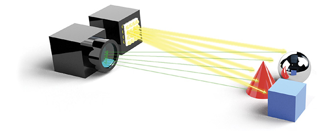
Time-of-flight 3D scanning is another active sensing method, calculating 3D information by measuring the round-trip time of light to objects in the scene. There are two basic versions of 3D time-of-flight sensors.
The first, pulsed time-of-flight lidar, emits short, powerful laser pulses. The challenge is to accurately determine the rising edge or peak of the returning pulses. The pulses are in the several-nanosecond range, but light travels 30 cm (~1 ft) per nanosecond, meaning that, for example, a 3-ns pulse is 90 cm (~3 ft) long. High-speed receive electronics are needed to determine the same measurement spot on the pulse when measuring the round-trip time. The accuracy of this approach is unsatisfactory, typically in the several-centimeter region.
Most time-of-flight sensors operate in the 850- to 940-nm NIR spectrum, and background photons from ambient light create noise. The range of these systems can be in the 100-m region and it is limited by eye-safety standards. Also, this measurement approach is sensitive to crosstalk from other 3D time-of-flight sensors.
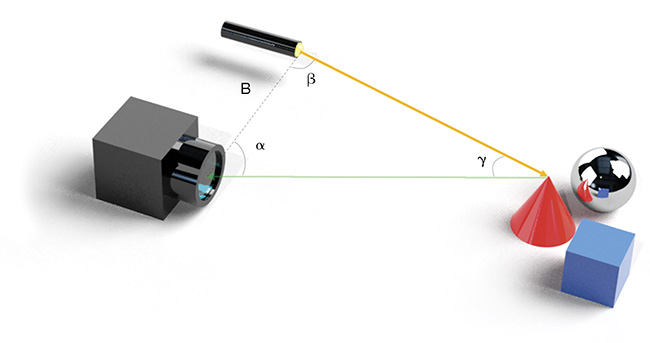
Triangulation is the underlying measurement principle for stereo vision and structured light. The base B is the known distance between the laser emitter and the camera device. The distance is calculated from the triangular relations. Courtesy of SiLC Technologies.
Pulsed time-of-flight lidar emits powerful pulses of light to detect obstacles in its path by measuring the round-trip time of photons that bounce back from objects. Courtesy of SiLC Technologies.
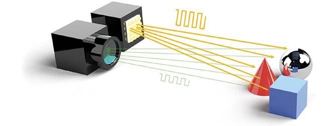
Phase-shift or amplitude-modulated time-of-flight 3D sensing measures the phase shift to the amplitude of the received signal. Courtesy of SiLC Technologies.
With multiple time-of-flight lidars operating in the vicinity, the time-of-flight system could become completely incapacitated by receiving pulses from other lidar systems. To remedy this issue, some time-of-flight lidar vendors are starting to introduce coding techniques by splitting the transmit signal into multiple pulses. However, range performance is proportional to peak power in these systems, and splitting the available energy into multiple pulses causes range performance to drop.
The second version — phase-shift, or modulated time-of-flight 3D sensing — works by modulating the continuous outgoing laser or LED illumination (for example, with a sinusoidal or square amplitude modulation) and observing the reflected light. The measured phase shift of the amplitude of the modulation between the illumination and the received signal is proportional to the distance.
The accuracy of this approach is slightly better than pulsed time of flight, but because of the longer measuring and integration time needed to determine the phase shift, and the distance ambiguity problem as the phase shift repeats itself, this solution is only good for shorter ranges.
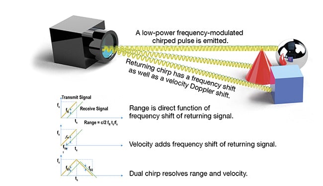
The principle behind FMCW 3D sensing. A low-power transmit chirp (green lines) is reflected off of an object. The frequency shift between the returning chirp (blue lines) is proportional to the distance and velocity of the object. An up chirp and a down chirp are used to resolve for both values: distance and velocity. Courtesy of SiLC Technologies.
Rather than relying on the time of flight of light pulses or the low-speed amplitude modulation of modulated lidar, an FMCW or coherent 3D sensing method emits and relies on a low-power frequency chirp from a narrow-linewidth laser coupled with a coherent receiver.
The reflected chirp contains the distance of the measurement point in the form of an optical frequency shift. If the measurement point also has a radial velocity, the reflected chirp adds a Doppler frequency shift.
Using an up-and-down chirp allows coherent lidar to instantaneously resolve both the range and velocity
of each pixel. Time-of-flight lidar lacks this ability to instantaneously resolve velocity that is expanding 3D sensing to 4D.
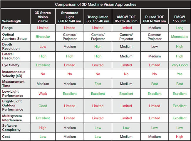
AMCW: amplitude-modulated continuous-wave; FMCW: frequency-modulated continuous-wave; TOF: time of flight. Courtesy of SiLC Technologies.
Coherent lidars, based on the FMCW technique, allow much higher detection sensitivity and accuracy. For FMCW lidar, the signal-to-noise ratio is proportional to the total number of transmitted photons and not to the peak laser power. FMCW lidar has more than 10× greater sensitivity due to coherent detection, while at the same time
transmitting at less than 1000× lower peak power than pulsed time-of-flight lidar.
The photonic circuitry of FMCW lidar mixes a portion of the outgoing coherent laser light with the received light. This provides a unique “unlock” key, effectively blocking any background radiation or multisystem interference.
In addition, the coherent mixing
of the local oscillator and the receive
signal provide an amplified beat
frequency through constructive interference before the signal is detected
by a balanced photodetector. The range is extracted by running a fast Fourier transformation on the received waveform.
Wavelength choice for illumination
For active 3D scanning methods, the choice of illumination wavelength plays a critical role in sensor performance.
There is good availability of low-cost semiconductor sensors that can detect visible light and near-infrared up to
940 nm. Eye safety is a significant consideration for active 3D sensors and, for these reasons, the visible wavelength is typically avoided. Even in the NIR spectrum, eye safety limits the power and range of 3D-sensing systems. Moreover, there is significant solar background irradiance in the 850- to 940-nm band, causing interference in outdoor bright daylight conditions. A far better wavelength is 1550 nm, where eye safety is up to 40× better and there is less interference from the sun.
Advancements in technology and reduced cost have resulted in 3D
vision becoming a critical technology
in industrial manufacturing automation — to enhance productivity, efficiency, and quality. As discussed, many competing technologies are available. The choice of technology is often decided by the applications, which range from general quality inspections, validations, verifications, and sorting, to safety and security.
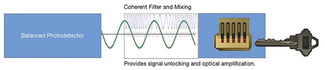
In coherent amplification, the local
oscillator, branched off from the transmit signal (blue), interferes constructively with the weak
receive signal (purple) and generates a new strong-beat frequency signal (green). The
strong-beat frequency signal is then fed back
into and detected by the photodetector. Courtesy of SiLC Technologies.
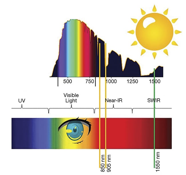
Commonly used lidar laser wavelengths
plotted on top of terrestrial solar irradiance
and the visible spectrum. Courtesy of SiLC Technologies.
FMCW promises to improve performance vectors in several dimensions, allowing for higher-precision scanning at longer ranges, while at the same time being eye safe and immune to outdoor lighting conditions or multisystem crosstalk. On top of this, it offers native 4D vision by providing velocity information with every measurement.
Components on a chip
The key challenge in creating an FMCW solution has been the low-cost, high-volume manufacturing of the high-performance components needed. The coherent approach requires lasers with long coherence lengths (narrow linewidths) and coherent processing of the light to extract additional information carried by photons.
This needs very accurate and low-noise optical signal processing circuits to form a coherent receiver. In addition, polarization plays a role here, as coherent beating will only work for photons of the same polarization. Wavelength stability and linearity of the laser source is critical over the measurement periods; otherwise, the signal-to-noise ratio can be degraded significantly.
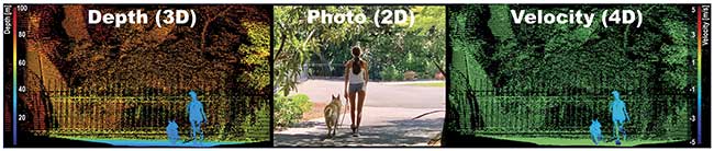
SiLC’s silicon photonics integrated 4D FMCW vision system provides depth and velocity data for every measured pixel. Depth point cloud (left),
camera image (center), and velocity point cloud (right). Courtesy of SiLC Technologies.
Creating such a stable, robust, and accurately defined optical system out
of discrete components is extremely difficult and expensive. SiLC Technologies Inc. offers a solution that integrates all needed optical functionalities into
a single silicon chip, using semiconductor manufacturing processes that are used to manufacture electronic IC chips.
In other words, the same approach behind the very complex electronic circuits integrated into a small silicon
chip, enabling consumer products at very low cost, can now be deployed
to make highly complex optical circuits for photonics applications.
The 3D vision space is fast growing, and there are many competing 3D
vision technologies. Ultimately the choice of technology is decided by the specific use case and the inherent cost and performance characteristics required for a successful application. FMCW is the newest of these technologies and is expanding the performance characteristics of vision systems on many levels — by extracting more
information than just intensity from
photons — even into the fourth
dimension.
Meet the author
Ralf J. Muenster is vice president of business development and marketing at SiLC Technologies Inc. Prior to joining SiLC, he was a director of Texas
Instruments’ CTO Office. He is a
multiple U.S. patent holder and has over 20 years of experience in the semiconductor and photonics industries; email: [email protected].
Reference
1. H. Weinberg (2019). Analog Devices. Presented at 2019 Microtech
Ventures Conference.