Athermalization involves modifying the optomechanical system to stabilize it to extreme or changing temperatures.
BORIS LANGE AND KYLE FIRESTONE, EDMUND OPTICS INC.
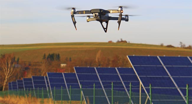
All matter expands and contracts in response to changes in temperature — imaging lenses are no exception. Standard-design lenses developed for machine vision systems perform well in temperature-controlled environments in applications where temperatures shift only slightly. But in high-performance vision systems that are subjected to extreme or wide shifts in temperature — such as autonomous systems operating outdoors, high-performance factory automation, and aerospace systems — the use of athermalized imaging lenses over standard imaging lens designs is becoming increasingly necessary to minimize temperature-dependent performance changes (Figure 1).
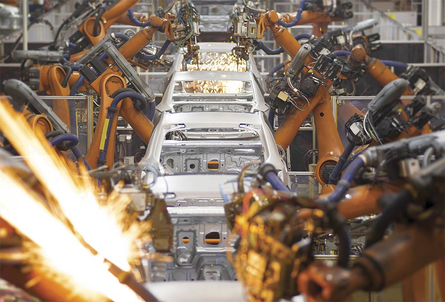
Figure 1. Imaging lenses used in applications exposed to temperature swings must be athermalized to withstand wide thermal shifts. This includes systems aboard drones (next image below), and across a wide variety of applications, including agriculture, transportation, and factory automation. Courtesy of Edmund Optics.
Machine vision is being integrated into more systems than ever before, such as autonomous agriculture equipment and factories, and many of these environments experience greater swings in temperature than traditional machine vision environments. Though the use of athermalized imaging lenses is becoming more commonplace, industry standards for the benchmarking of performance specifications — including storage, damage, and operational temperature ranges — have not yet become standardized, and neither have the test conditions or metrology equipment needed to obtain such specifications.
 Machine vision is being integrated into more systems than ever before, such as autonomous agriculture equipment and factories, and many of these environments experience greater swings in temperature than traditional machine vision environments. Though the use of athermalized imaging lenses is becoming more commonplace, industry standards for the benchmarking of performance specifications — including storage, damage, and operational temperature ranges — have not yet become standardized, and neither have the test conditions or metrology equipment needed to obtain such specifications.
Optical design challenges
All materials that experience a temperature change will expand or contract. The amount by which materials change in dimension can be determined using the empirically derived data reported by material manufacturers on their datasheets. Equation 1 shows the coefficient of linear thermal expansion (CLTE).
In practice, notably for small temperature changes, the differential terms for the change in length and the change in temperature (dL and dT, respectively) are typically well approximated by
differences (ΔL and ΔT, respectively).
While Figure 2 shows a material expanding in only one dimension,
materials expand in every direction. Thus, material cross sections and volumes also change.
Equation 1:
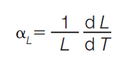
The CLTE is dependent upon the length of the material (L) and the reciprocal
of the temperature gradient along that characteristic length  , where: , where:
• The CLTE is typically indicated with the symbol αL and specified with
reciprocal temperature units (for example,  ). ).
• L is the material length.
•  is the reciprocal of the temperature gradient with respect to length. is the reciprocal of the temperature gradient with respect to length.
Equation 2:
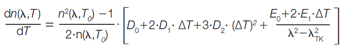
The refractive index gradient with respect to temperature is a function of initial temperature, final temperature, and the wavelength of light (in a vacuum).
The equation model takes a form that is dependent upon several other
experimentally determined constants and a reference temperature, where:
• n is the refractive index of the material.
• ΔT is the temperature difference (T − T0).
• T0 is the reference temperature (usually 20 °C).
• λ is the wavelength of light in a vacuum.
• D0, D1, D2, E0, E1, and λTK are all empirically fit material constants.
|
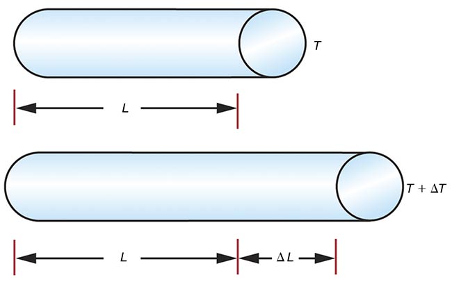
Figure 2. Changes in temperature (T) lead to changes in the length of a material (L) based on the coefficient of linear thermal expansion (CLTE) of the material. Courtesy of Edmund Optics.
For isotropic materials — such as most bulk, nonrolled metal and most glass — the area thermal expansion coefficient (αA) is 2× the CLTE, and the volumetric thermal expansion coefficient (αV) is 3× the CLTE. These
different coefficients are useful for doing calculations with different geometries as thermal systems evolve over time. Note that the generalized term for each of these coefficients is the coefficient of thermal expansion (CTE).
When subjected to the same temperature changes, metals typically expand and contract more than ceramics and glasses but less than plastics. It is important to note that dimensional changes due to temperature will often change the radius of curvature and thus the optical power of lens elements. Additionally, for all transmissive materials (for example, glass), refractive index also changes with temperature. Equation 2 shows the complexity with which this change is modeled.
Changes in mechanical dimensions and refraction are two of the main properties to consider with changing
temperatures. Because imaging
assemblies consist of a series of glass elements seated in groups that are housed within a larger metal barrel, there are additional effects that can be considered for inclusion in optomechanical and optothermal models. Some of these additional factors include changes to optical aberrations (of the many aberrations, defocus is typically the most usefully modeled) and focal length (Figure 3).
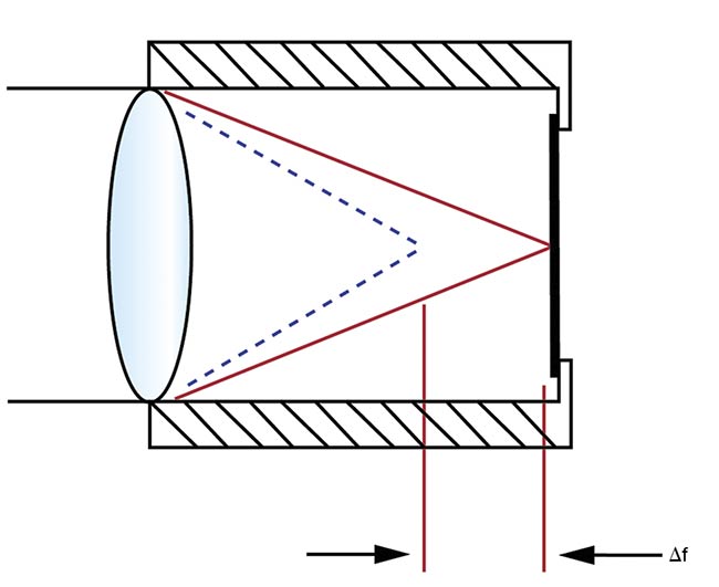
Figure 3. The net mechanical and optothermal effects from changing temperature can result in a change to the focal length of a lens. Courtesy of Edmund Optics.
When exposed to extreme or changing temperatures, uneven expansion
of the materials can cause optical
elements to tip, tilt, and become decentered along the optical axis (Figure 4).
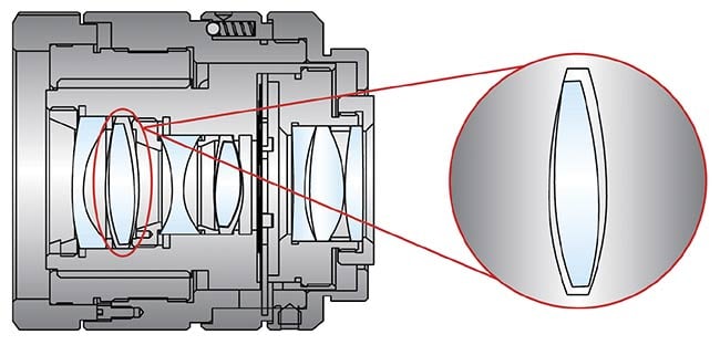
Figure 4. When optical elements are not held securely in the barrel assembly, they can experience roll due to diameter error from thermal expansion. Courtesy of Edmund Optics.
There are infinite ways to predict how these effects can stack up, depending on the order and grouping of elements (Figure 5).
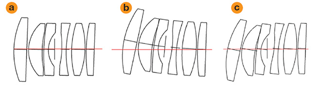
Figure 5. Lens elements tilt independently (a). Tilts and decentration are accumulated in the order of assembly (b). Tilts are accumulated in the order of assembly but with no additional decentration. This motion is called shearing (c). Courtesy of Edmund Optics.
For optical elements grouped together within the assembly barrel, the experienced effects of tip, tilt, and decenter are to a degree shared. These effects may stack in many circumstances, but not in others (Figure 6).
In cold-temperature environments, metal lens assemblies can contract significantly, applying stress to the
optical elements within. In the best-case scenario, the stress is well tolerated by the element or elements, though stress can directly degrade image quality.
In some cases, applied stress can overwhelm the elements, chipping them at their edges or shattering them entirely. If chipping occurs outside of the clear aperture of the optical elements, then imaging performance may not be affected much. However, all of these effects can individually degrade system performance, and broken or shattered lens elements can render lens assemblies completely inoperable. Cold temperatures typically cause more serious issues than high temperatures. However, when metal assemblies
expand more quickly than the optical elements within, the decenter tolerances decrease due to an increase in size of the bore gap between the
assembly and the lenses. To combat the effects of conflicting CTEs and
refractive index changes, imaging lenses are athermalized.
Designed for extreme temperatures
Athermalization refers to the process by which an optomechanical system
is stabilized to extreme or changing
temperatures, and it also describes
the optomechanical system that under-
went the process. The process can be active or passive. An imaging lens that has been actively athermalized is designed to withstand the extreme or changing temperature so that the lens is not critically damaged, though it may not perform at the nominal or optimal specifications. The active process results in an imaging lens that may require additional intervention, such as a refocus or working distance adjustment. Conversely, a passive athermalization imaging lens has been designed such that the net thermal effect of all the mechanical and optical changes in the materials is accounted for over the range of temperatures specified. This type of athermalization results in a lens that requires no additional intervention or compensation to maintain performance within the designated specification.
To specifically combat the chipping or shattering of optical elements within drop-together lens assemblies, lens designers amend the manufacturing process to allow larger-than-standard bore gaps that can accommodate for material expansion or contraction
without endangering the optical components within. Standard-design imaging lenses typically feature a bore gap on the order of 10 µm. Increasing the size of the bore gap, however, means that the optical elements within the optical train potentially have more room to decenter than with standard bore gap sizes. Increasing the bore gap additionally requires the size of the outer assembly barrel to also increase. An alternative option to combat decenter and misalignment of optical components is to use somewhat larger bore gaps in conjunction with active alignment manufacturing techniques (Figure 6). Active alignment is extremely effective in reducing tip, tilt, decenter, and other misalignment types, but it requires expensive customization,
because standard and off-the-shelf
imaging lenses are typically manufactured as drop-together assemblies without active alignment (Figure 7).
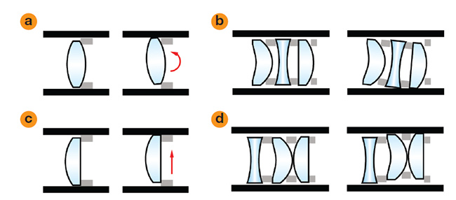
Figure 6. Roll of a single lens element (a). Roll of coupled lenses (b). Decenter of a single lens element (c). Decenter of coupled lenses (d). Courtesy of Edmund Optics.
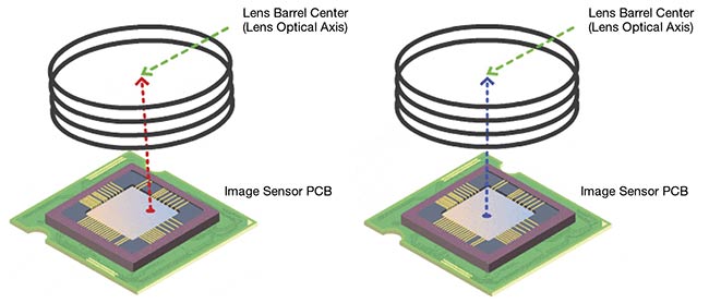
Figure 7. The lens barrel center is misaligned with the center of the image sensor printed circuit board (left). The centers of the barrel and sensor have been aligned to one another with active alignment (right). Courtesy of Edmund Optics.
Measurements and metrology
There are international industry
standards for many types of ruggedization and for ingress protection, which refers to protection against solid and liquid intrusion. These standards often list the ratings for various amounts of protection from environmental factors and also list the necessary testing
conditions required for products to meet such ratings (see IEC 60529, https://webstore.iec.ch/publication/2452). Lens design software — such as Zemax and CODE V, in conjunction with CAD software — is often used to simulate or model optomechanical and optothermal performance of imaging lenses. Though simulating thermal effects does provide some insight into how a lens design will respond to thermal changes, these simulations are quite limited in scope and are often inaccurate.
Imaging lens manufacturers that specify performance metrics for given temperature ranges should be able to guarantee such performance via empirically obtained data collected from testing lenses in state-of-the-art thermal performance test chambers. However, using chambers to test lenses is typically a slow process, as unsteady temperature adjustments can result in uneven thermal gradients across the various materials of the lens. Therefore, thermal data is typically only collected for one temperature extreme or for as narrow of a temperature range as the environment of the use case necessitates.
While the ambient temperature of the test chamber is varied, a test bench records the change in one or more of the critical operating parameters. For most imaging lenses, including fixed focal length lenses, the most useful parameter is the modulation transfer function (MTF). MTF is the optical transfer function that correlates how the contrast of the image that the lens creates changes at different spatial frequencies or resolutions (Figure 8).
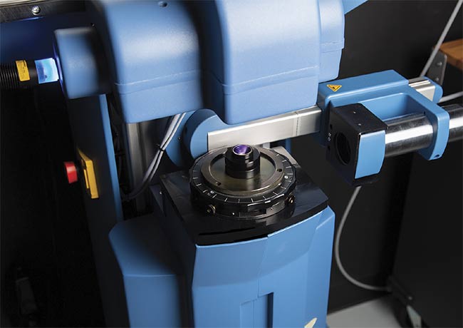
Figure 8. An imaging lens is tested in a commercially available TRIOPTICS modulation transfer function (MTF) test station. Courtesy of Edmund Optics.
The resulting MTF curve allows the end user to predict lens performance at any temperature within the designated range. Analysis of additional parameters for other lens types is sometimes needed, such as the change in chief ray angle for telecentric lenses or beam pointing. However, these measurements are much less common.
System performance and mounting
When subjected to the same temperature changes, metals typically expand and contract more than ceramics and glasses but less than plastics. It is important to note that dimensional changes due to temperature will often change the radius of curvature and thus the optical power of lens elements.
What is ultimately most important is achieving system-level performance. Without careful consideration of the mounting of the imaging lens to the camera, the optical design — whether athermalized or not — may not matter. It is therefore critical to consider the material and CLTE of the camera and lens mounts to understand the effects of temperature-induced defocus. To account for this defocus in simulations, a fixed point is designated somewhere on the mechanical structure to which all other surfaces are referred. Designating this point is easier for common lens mounts with a defined flange, such as the C-mount or TFL-mount, but is considerably more difficult for lenses with other mounts, such as the M12 lens with an S-mount, which must be manually focus-adjusted to the sensor via the mount threads. For this reason, athermal lens designs are easier to achieve within the context of custom lens design projects, rather than for general purpose, off-the-shelf lenses that may end up on any camera and in any application environment.
Machine vision is utilizing imaging
systems in applications that push the limits of standard imaging lenses. Extreme and changing temperatures require that vision systems be desensitized to temperature changes or compensated for by design. Athermalization can result in varying degrees of protection for imaging lenses. Some of these levels of protection are much costlier and require more testing time than standard lenses require. This is why it is usually more practical to consider athermalization for custom imaging lenses that are designed from scratch, rather than retrofitting standard or off-the-shelf lenses, although lens manufacturers are beginning to design and manufacture off-the-shelf athermalized imaging lenses. In any case, it is important to understand system-level application requirements and to maintain close communication between the lens manufacturer and customer.
Meet the authors
Boris Lange, Ph.D., manager of imaging for Europe, is responsible for Edmund Optics Inc.’s imaging business and its development in the region. Since joining the company in January 2015 as an imaging solutions engineer, Lange has supported European customers with technical guidance and application support for imaging and machine vision systems, and he was actively involved in forming a dedicated European imaging team. Before joining Edmund Optics, he gained valuable experience as an optical designer in the analytics business unit at Polytec, developing VIS, NIR, and Raman spectrometers. Lange holds a doctorate in physics from Mainz University and GSI
Helmholtzzentrum, with a focus on heavy-ion research. His thesis
examined coherent EUV light sources generated by high-energy lasers;
email: [email protected].
Kyle Firestone is a technical marketing engineer at Edmund Optics Inc., where his roles include creating technical content and developing marketing strategies for the imaging business unit. He received a Bachelor of Science in chemical engineering from Rowan University in 2017; email: [email protected].