A combination of advanced packaging and LED chip technologies, optimized light extraction and improved optical aspects of LED-based projection light engines can greatly improve brightness.
Stefan Groetsch, Osram Opto Semiconductors GmbH
Increasing the output performance of LED-powered projectors is within our grasp. When the first LED-powered projectors were commercialized, they generated interest because of new properties and features such as permanent lamps, superior battery operation, higher color gamut and fanless cooling. However, these first units delivered only 10 to 15 real lumens, a brightness level that allowed only paper-size projections. Since then, product development has combined technologies to increase brightness.
Chip performance increases when higher-reflective internal mirrors are combined with thinner epitaxial layers, causing less internal photon reabsorption as light travels through the chip. A textured surface recently developed by Osram Opto Semiconductors GmbH of Regensburg, Germany, negates the prior limitations of total internal reflection by scattering reflected light back into the chip. By the time light is reflected back to the top surface at the internal mirror, it typically can escape the die. Yet, by increasing the current spreading capability of the epitaxial layers, the efficiency of the LED at higher currents does not drop as dramatically as that of conventional structures. By optimization of the contact geometries and of the thermal resistance of the dies, the thermally induced rollover of InGaAlP LEDs is enhanced from about 1.5 A/mm2 to far beyond 3 A/m2.
Achieving this improved chip performance also requires package improvements, as shown in a design where six power LED chips are mounted to a highly thermally conductive ceramic heat sink (Figure 1). This heat sink is attached directly to a metal-core printed circuit board, which also contains a connector, surge protection devices and a temperature sensor. Changing the interconnect material, as well as replacing the aluminum core material with copper, decreases thermal resistance. In fact, a finite-element simulation predicted a drop from 2.78 K/W to 1.73 K/W. These values also can be demonstrated in thermal resistance measurements where the old assembly version shows 2.75 K/W, and several new components show only about 1.8 K/W. Even more importantly, the new concept maintains that low value even after 1000 thermal cycles from –40 to 100 °C.
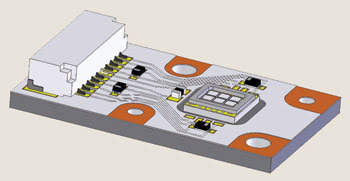
Figure 1. This Ostar LE × H3A for projection light engines has six power LED chips mounted to a ceramic heat sink, which is attached to the core of a metal-core printed circuit board. The circuit board has a connector, surge protection devices and a temperature sensor.
Additional improvement comes from implementing an enhanced light extraction that raises the total flux from a green or blue LED package by about 25 percent while simultaneously decreasing red emission by only a few percent. The new light extraction also creates additional directionality, with total emission within ±80°. This leads to a collected flux ratio within ±60°, increasing the likelihood that most current optics can pick up the light. This even overcompensates for the slight drop in red emission.
On-screen lumens are not defined by the light source only. There also are trade-offs at the light engine level that are dictated by the law of etendue conservation.
Esystem = π • n2system • sin2 (θsystem) • Asystem
The etendue of the projector’s microdisplay is determined by its area A and the angle ±θ at which the lens system can project to the screen. The refractive index n is important, but in most cases, the reference media is air.
The formula can be used to determine the usable LED source area. Some LEDs are lambertian emitters and emit at a level of ±90°. If we assume that the optical system collects the light over the entire angle, the etendue equation defines the maximum usable LED area. However, almost no optical system can collect all of the light. Therefore, it is better to cut off higher radiation angles and to increase the chip area.

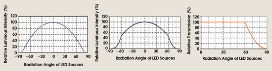
Figure 2. The left curve shows the angular intensity distribution over the angle of the device. The middle diagram shows that the efficiency for a hypothetical lens system is set to unity from 0° to 60° and drops to zero at 90°. The right diagram shows the folding of both diagrams and describes the angular intensity transported through the system over the emission angle of the LEDs.
The best approach to optimize the system is to fold the angular intensity distribution with the relative angular transmission of the optical system, where the efficiency for a hypothetical lens system is set to unity from 0° to 60° and drops to 0° at 90° (Figure 2). For a collection angle from 30° to 60°, the gain is stable at about 20 percent, but with a varying chip area (Figure 3). For example, the solution with a 6-mm2 chip area and a 55° collection angle offers 20 percent higher system brightness compared with one with a 4-mm2 chip area and a 90° collection angle.
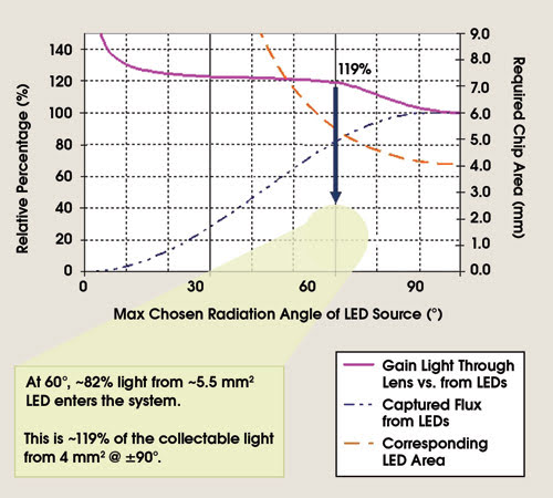
Figure 3. The collection angle is varied from the LED source from 0° to 90°. The blue line shows the percentage of captured flux from the LED source. The orange line shows the corresponding usable chip area for a microdisplay with a 0.55-in. diagonal. The pink line shows the relative system efficiency.
Finally, we compared three illumination configurations for projectors. One was a single-channel single-LED module with three colors on one board, which allows a simple one-to-one replacement of a lamp with the LED module.
The second approach of a two-channel illumination configuration requires only one dichroic mirror to superimpose the green light from one module with the mixed blue and red light from a second module.
In the third approach, two optimized dichroic mirrors combine the light of three monochrome LED modules. The estimated on-screen flux is based on the previously discussed LED improvements, a digital light processing-based projector using a 0.55-in. imager and a light engine efficiency of 22 percent (Figure 4). Without special driving schemes for the LEDs in a pure sequential operation of the colors, the single-channel delivers more than 50 lumen, the two-channel gives more than 100 lumens, and the three-channel solution surpasses 150 lumen.
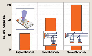
Figure 4. On-screen lumens are shown with various illumination regimes for the projector output.
These developments open the door for next-generation LED projectors in the range of 150+ lumens on-screen. With optimized systems, LED projectors of 200 to 300 lumens are possible in the next year. They match the brightness of many installed home theater projectors and offer all the advantages of LEDs, such as color gamut and a longer-lasting light source, compared with the other projector components.
Meet the author
Stefan Groetsch is a senior engineer in the power LED engineering division of Osram Opto Semiconductors in Regensburg, Germany; e-mail: [email protected].