New process results in an optical fiber with UV attenuation approaching the intrinsic theoretical limit.
Joe Zhou, John Shannon and Jim Clarkin, Polymicro Technologies
Raman spectroscopy with in situ UV optical fiber probes, UV confocal laser scanning microscopy using optical fiber-laser coupling, and UV fiber optic spectroscopy for gas chromatography are just a few of the applications using optical fiber as a waveguide to deliver UV light. Having a high-transmission (low-attenuation) UV fiber is beneficial because high transmission reduces the power requirement for the UV light source, extending its lifetime. Often, an instrument is made possible only with thin, flexible and easy-to-use optical fiber.
Stable UV output is a key to successful instrument performance. However, the lamp frequently is switched off between uses to preserve the lamp life and to reduce UV degradation of the fiber. The instrument must be ready for use quickly after it is switched on. Therefore, the fiber must be stable over many on/off cycles.
In addition, the instrument must be stable and free from light-intensity changes for several hours of use. In spectroscopic instrumentation, once an instrument has been calibrated, stable fiber transmission may reduce or eliminate the need for re-calibration throughout the instrument lifetime. To accomplish this, the UV optical fiber must be highly resistant to degradation caused by UV exposure.
UV optical fiber
Standard UV optical fiber has a high hydroxyl (-OH) pure silica core with a doped silica cladding. The glass preform for the fiber is drawn at a temperature of about 1900 °C. Common fiber core sizes range from 50 to 1000 μm. From select high -OH preforms, enhanced UV fiber can be produced with improved optical transmission. In these fibers, UV transmission is limited by two factors:
• intrinsic attenuation from Rayleigh scattering, electronic transitions and a nonstructured -OH absorption tail below 200 nm.
• additional losses resulting from UV defects originating from the breaking of strained bonds under UV or gamma irradiation producing nonbridging oxygen hole centers and in electronic centers peaking at absorption bands at 265 and 214 nm, respectively. (The electronic centers are also called e' centers, and they are a type of defect in an atomic lattice.)
Besides the glass material itself, the fiber draw process and postdraw fiber treatment affect the UV performance of the fiber. UV fiber can be improved further with an additional step of diffusing hydrogen into the fiber after it is drawn.
With a dramatic increase in hydrogen concentration, the defects are “neutralized,” resulting in a fiber that exhibits extremely high UV transmission (low attenuation). As a drawback, however, the fiber suffers severe degradation of UV performance as hydrogen diffuses out of the fiber over time. The degradation rises exponentially with decreased fiber core size. The hydrogen-treated fiber does improve initial UV transmission performance and may be reasonably good for some applications but may not be acceptable when highly stable UV transmission is required.
To produce a more stable UV fiber, it is critical to reduce the hole-centers and the e' centers and to passivate the remaining defects in the glass fiber. A recent development has led to the creation of a highly stable UV optical fiber with UV attenuation approaching the intrinsic theoretical limit (Figure 1). This is achieved through a proprietary process.
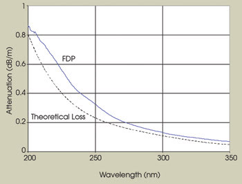
Figure 1. The UV attenuation of a highly stable UV fiber (FDP) approaches the intrinsic theoretical limit.
Fibers sometimes are pretreated with UV light, and these are deemed more “stable.” Although a fiber treated in this manner may see less attenuation change over time, in reality this is because the UV treatment has induced an irreversible attenuation increase so that the user already is starting with a fiber that has high attenuation.
This is not the case with the highly stable UV fiber, dubbed FDP, which is manufactured by Phoenix-based Polymicro Technologies, a subsidiary of Molex Inc. of Lisle, Ill. The fiber shows an improvement in UV transmission and stability compared with standard and enhanced UV fibers (Figure 2).
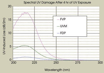
Figure 2. The UV-induced loss of FDP fiber is compared with that of standard UV (FVP) and enhanced UV fiber (UVM).
Near 214 nm, the fiber attenuation is approximately 8 dB/m, or 2 dB/m more transparent than standard and enhanced fibers. It is interesting to note that the fiber has a consistently low attenuation, whereas the standard UV fibers vary widely from lot to lot.
This fiber is significantly more stable than enhanced UV fibers within a period of 18 h after the first 4 h of UV exposure (Figure 3). Several hours after the deuterium lamp is first turned on, the fiber attenuation rises and levels off and remains stable for many days after repeated on/off cycles of the lamp. The enhanced UV fiber shows a greater attenuation increase after the lamp is turned on each time, which may cause trouble in measurement repeatability and in instrument calibration.
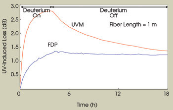
Figure 3. The effect of UV exposure on FDP fiber against UVM at 214 nm indicates no changes of UV-induced loss for FDP but large changes for UVM from on/off cycles of the deuterium lamp after initial UV exposure.
This fiber is useful for UV fiber optic applications where the light source experiences regular on/off cycles and where high transmission and stability are desired. Furthermore, it has opened a window for instrument applications in the deep UV (∼200 nm), which previously were considered impossible with optical fiber. Future developmental efforts will be made to push the operating wavelength below 190 nm.
Meet the authors
Joe Zhou is the optical fiber product manager, John Shannon is a senior project manager, and Jim Clarkin is vice president of engineering and business development at Polymicro Technologies in Phoenix, a division of Molex Inc.; e-mail: [email protected].