Reducing loss levels with photonic crystal fibers opens up opportunities in telecommunications and other fields.
Hendrik Sabert and Jonathan Knight, BlazePhotonics Ltd.
Photonic crystal fibers are glass fibers with a fine array of airholes running down their length. They can exhibit photonic bandgaps, and the more-than-a-decade-old concept of using a two-dimensional bandgap to trap light in a hollow-core fiber is on the verge of competing successfully with conventional fiber in some applications.
Universities, major corporate laboratories and start-up companies around the world are modeling, fabricating and testing variants of bandgap-confined hollow-core fibers. It is clear that some of the limitations of conventional fibers can be readily overcome by using these new structures; for example, low nonlinearity and controllable dispersion offer unique opportunities for fiber-based short-pulse delivery through hollow-core fiber.
One key objective of the research effort is to achieve the “holey” grail of hollow-core photonic crystal fiber technology: to reduce loss to a level below what is achievable with conventional silica fibers, possibly while simultaneously improving other fiber properties. If this should succeed, these fibers could bring about a paradigm shift in optical telecommunications. But even at the existing state of development, they are beginning to find applications in a variety of scientific and engineering fields.
How they work
The principle behind conventional optical fibers is simple. Total internal reflection traps light in a core, which has a higher refractive index than the surrounding cladding material, which must have a refractive index of less than one to guide light in air or a vacuum.
In hollow-core fibers, the cladding consists of a material that has a photonic bandgap in the wavelength range of interest to trap the light inside. Photonic bandgaps do not occur in natural materials, but can be engineered into artificial “photonic crystal” materials by forming a periodic array of airholes with the correct size and spacing. Their working principle is analogous to that of semiconductors, where the crystal’s periodicity leads to a bandgap for electrons.
The numerical results show the existence of a 2-D photonic bandgap in a structure consisting of a triangular array of airholes embedded in a silica matrix (Figure 1). The bandgaps in hollow-core fibers are not complete: They do not prohibit propagation in all directions, but cover a finite range of values of the propagation constant. For some values of the propagation constant, the bandgaps can extend to an effective index of less than one, the index of a vacuum. This means that bandgaps can reflect light incident from a vacuum or air.
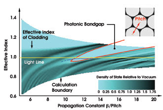
Figure 1. In hollow-core fibers, light is confined to the core by constructive interference of rays reflected at the glass-air interfaces in the cladding. For a triangular array of circular airholes in a silica matrix, the calculated density of states in the photonic bandgap drops to zero. Light cannot propagate in the cladding. The diameter of the holes in this example is 94 percent of the pitch. The blue line indicates qualitatively the position of the fundamental mode in the core.
Hence, by embedding a hollow core within such a photonic bandgap material, one can hope to form a hollow-core waveguide in which light is confined to the core because it cannot propagate in the cladding. Although light is present in the cladding, it does not propagate in the direction perpendicular to the fiber axis. The multiple reflections off the periodic index steps cause the field to be evanescent in the perpendicular direction.
In many ways, the photonic bandgap cladding behaves like an ideal conductor, and around the center of the bandgap, hollow-core fibers can be treated like metallic waveguides but at optical frequencies.
There are two notable differences between the bandgaps in the cladding of a hollow-core fiber and the in-plane bandgaps being developed for planar applications. First, the formation of in-plane bandgaps requires very large contrasts in refractive index, limiting the choice of materials. In the case of photonic bandgap fibers, where the light travels almost parallel to the index boundaries, a refractive index ratio of less than 1.5:1 is sufficient to form bandgaps of practically interesting width. Airhole fibers can thus be made from silica glass, the staple material of conventional fiber technology. Secondly, the hole spacing or pitch can be several times the optical wavelength. For example, for a fiber operating at 1550 nm, a pitch of ~3 μm is sufficient, considerably simplifying fabrication.
The most widely used method for fabricating photonic crystal fiber is to stack silica capillary tubes by hand to make a preform (Figure 2, top). The core is embedded by omitting several capillaries from the center of the stack. Typically, several hundred capillaries are stacked in a close-packed array and inserted into a jacketing tube to create a fiber preform.
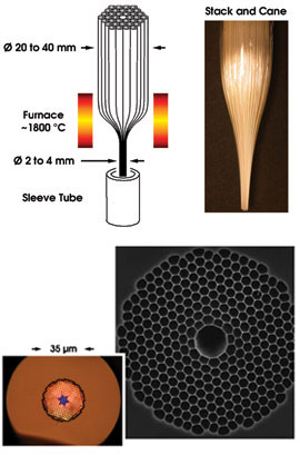
Figure 2. In the stack-and-draw process (above), thin-walled silica capillaries are stacked and drawn down to a cane of a few millimeters in diameter. The cane is then inserted into a silica sleeve tube and drawn down again to a fiber of typically 125 μm in diameter. In the back-illuminated optical micrograph and scanning electron microscope image of the photonic crystal fiber region of two similar hollow-core fibers (below), the blue light propagates in the hollow core in a higher-order photonic bandgap.
In the laboratories at BlazePhotonics Ltd. in Bath, UK, this preform is drawn to fiber in two stages, adding a second jacketing tube before the final draw. The extra jacket enables creation of fibers with a standard outer diameter, while providing independent control over the photonic bandgap pitch and, hence, the operating wavelength. Draw lengths of a few kilometers are typical, but there are no known limits to drawing much longer fiber.
Optical properties
• Mode fields. As in conventional fibers, the favored mode in silica-based hollow-core photonic bandgap fibers has a quasi-Gaussian modal field distribution. Besides being most compatible with laser sources, this mode has an excellent overlap with conventional step-index single-mode fibers. An overlap of more than 99 percent is possible. The fundamental mode also has the smallest overlap with the glass — in a fiber with a seven-cell defect (Figure 2, bottom), we have observed considerably more than 95 percent of the light to travel in air, and for larger cores such as one formed by omitting 19 capillaries, numerical simulations show that 99.5 percent of the light can be excluded from the glass. The decay of the field of the guided mode in the cladding region can be very rapid — typically up to 10 dB per cladding period — so that low levels of confinement loss are attainable with a practical number of periods.
• Attenuation. Losses of state-of-the-art conventional fiber for the 1550-nm range are about 0.2 dB/km and, for 1060 nm, about 1 dB/km. The best reported loss for index-guiding photonic crystal fiber is on the order of 0.5 dB/km for solid, as opposed to hollow, core.
The initial hollow-core bandgap fibers had losses of about 20 dB/m, but losses have fallen dramatically over the past three years, and the record loss to date is 13 dB/km, or less than 30 dB/km over a 125-nm-wide wavelength band centered around 1450 nm.
In a typical attenuation curve for a hollow-core fiber designed for the 1060-nm region, a low-loss window of roughly 15 percent of the central wavelength is surrounded by higher-loss regions, which typically cover the rest of the optical-frequency range (Figure 3). Bend loss in these fibers is simply not an issue. In structures such as those shown, it is practically unobservable with even a large number of millimeter-scale bends.
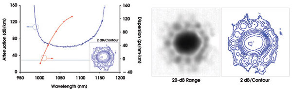
Figure 3. Attenuation, chromatic dispersion and near-field intensity were measured after 100 m of fiber for the fundamental mode. The form overlap with the fundamental mode of a conventional step index fiber is greater than 95 percent.
These results represent excellent progress but are still some way off the known fundamental limitations. The low polarization of air and the small overlap with the glass in hollow-core fibers suggest that losses well below that of state-of-the-art conventional fibers might be attainable. On the other hand, coupling to cladding modes or to higher-loss confined modes could result from variations in the fiber along its length and from surface roughness — even on the atomic scale. However, the impact of the limiting loss mechanism will depend strongly on the overlap of the guided mode with the glass and its interfaces with air. Because small changes in the fiber design can have an unexpectedly large impact on the modal properties, significant performance gains remain to be made.
• Dispersion. The group-velocity dispersion in hollow-core fibers is dominated by waveguide dispersion, while the material dispersion of silica in conventional fibers is key to the overall dispersion. The material contribution to the dispersion in silica fibers has played a major role in determining the developmental path of fiber optics; it has also been a major limiting factor in certain applications and plays virtually no role in hollow-core fibers.
Hollow-core dispersion passes through zero within the low-loss transmission window, enabling the design of fibers with normal, near-zero or anomalous dispersion at any given wavelength. The dispersion is low and anomalous over much of the guiding band, which makes it possible to propagate solitonlike pulses along the fiber. Because the nonlinear phase shift from gases is far lower than that of silica, the fundamental soliton energy is much higher than in conventional fibers. The implication is that hollow-core fiber could offer an almost ideal solution to the problem of fiber-based delivery of pulses in the 100-fs range.
Hollow-core fibers are ready to move out of the foundry and into research laboratories for applications development. As one example, it was shown recently that a hydrogen-filled hollow-core fiber can act as a gas cell for stimulated Raman scattering at record low pump intensities (Figure 4).
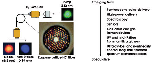
Figure 4. Hollow-core fiber allows an increase in the interaction volume between an optical mode and gases or liquids almost limitlessly, reducing the threshold for nonlinear interactions to raising the sensitivity of spectroscopic experiments. In this case, the threshold power for the generation of stimulated Raman radiation in H2 gas is reduced by more than 1000 times when compared with conventional gas cells.
One application area is in the transmission of “exotic” wavelengths in the IR or UV. In these ranges, it is hard to find materials with sufficiently low loss. The potential in the UV is still unproved because of difficulties in fabricating small-enough structures, but the technology is promising for the mid-IR range using soft glasses, with applications in medical equipment and sensors.
Meet the authors
Hendrik Sabert is vice president for research and development at BlazePhotonics in Bath, UK.
Jonathan Knight is a founder of BlazePhotonics.