As research on head-up display and augmented reality systems advances, more sophisticated optical systems will enable better user experiences.
PIERRE-ALEXANDRE BLANCHE, THE UNIVERSITY OF ARIZONA
Combiners are semitransparent surfaces used in head-up display (HUD) and augmented reality (AR) systems to overlay an image presented by a projector on top of the viewer’s physical world. The combiner is transparent and lets the viewer see through it, while simultaneously reflecting dynamic digital information.
Over the years, combiners have evolved from simple semitransparent flat surfaces that passively reflected light from projectors to sophisticated conformational holograms that diffract selective wavelengths and act as relay lenses. This evolution has been driven by a desire to maximize the field of view (FOV) of the projected image, to maintain a comfortable eye box, and to minimize the size of the projector. These same constraints have motivated
a transformative revolution in combiner design, which utilizes a waveguide instead of free-space optics.
Direct reflection
New AR and HUD systems are offered to the public on a regular basis. Current systems feature a smaller form factor and better optical characteristics than were possible as recently as a year ago. The key enabler for this new technology is a combiner element that uses both holograms and waveguide properties to achieve large FOV and eye box.
From an optical perspective, AR and HUD systems are very similar; viewers see a projected image overlaid on their physical worlds. This feat is achieved using a semitransparent combiner element positioned in front of the viewer that reflects a projected image toward the eyes (Figure 1).
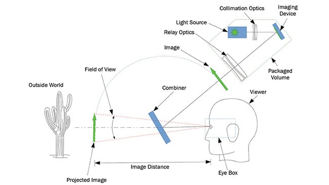
Figure 1. Working principle of a head-up display (HUD)/ augmented reality (AR) optical system. A projection system creates an image that is overlaid to the outside world by a semitransparent combiner. Courtesy of Pierre-Alexandre Blanche.
The simplest of all combiner technologies is just a flat piece of transparent material that redirects an image using Fresnel reflection, which is the result of an index difference between the material and the air. This simple reflection phenomenon can be used in a car by placing a cellphone near the windshield. Most navigation apps have an HUD mode that flips the image to allow this usage.
One problem with this crude approach is that there are reflections from both front and back surfaces of the material, which double the image (Figure 2). To prevent doubling, an antireflection coating can be applied on one of the materials’ surfaces.
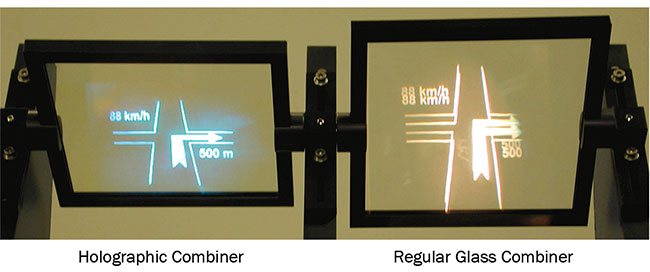
Figure 2. A holographic combiner (left) and a regular glass combiner (right). Note the doubling of the image in the case of the simple glass combiner. Courtesy of Pierre-Alexandre Blanche.
To increase the image visibility and make it more comfortable to see in broad daylight, the reflection from the glass
(~10 percent at 45°) can be enhanced with a reflective coating applied on one side
of the combiner. If the coating is broadband, however, such as a metallic coating, it decreases the natural light passing through the combiner, which can cause
a problem when the system is used at night or at low ambient intensity. To avoid this drawback, a more sophisticated coating such as a notch filter, which reflects only narrow wavelength bands, can be used. The bands of the filter are designed to match the projector’s light source, such
as diodes, which increases the reflection of the projected image while maximizing the transmission of the natural light.
Another issue with an approach that relies on direct reflection from glass arises when the combiner’s surface is not flat, but curved. In this case, the reflection distorts the image, and an optical precompensation should be applied. This precompensation can take the form of more optics in the projection system, which may include freeform elements to ensure good image quality. To avoid such expensive components, the reflective function of the combiner can be obtained using a holographic optical element (HOE) that diffracts the image back to the viewer regardless of the shape of the surface to which it is affixed.
HOE combiners
HOEs are thin optical elements that use the principle of diffraction to transform an incident wavefront into another, predefined wavefront. They can be made to act as lenses or as nonflat mirrors, and have uses in many optical systems, such
as for gun sights and null lenses.
HOEs can be manufactured using a holographic setup where two mutually coherent laser beams interfere with one another inside a holographic recording material. Examples of such material are photopolymer, silver halide, or dichromated gelatin. Alternatively, the profile of an HOE can also be computed and then transferred on a material using a lithography technique. In this case, grooves are etched on the top of the material to produce a surface-relief profile.
It should be pointed out that an HOE is a permanently recorded element that does not diffract any image by itself, like a 3D hologram would. The HOE acts as a semitransparent mirror, reflecting the image provided by the projector. As such, when the projected image changes, the image perceived by the viewer changes accordingly, without the HOE needing to be adjusted. Similarly, an HOE combiner does not provide 3D images, per se. For 3D images to be displayed, the combiner — HOE or not — should be coupled with a 3D projector, either stereoscopic or holographic.
Used as combiners, HOEs have several advantages over other technologies: They can be recorded on curved surfaces, they can diffract at an angle different from
the reflection angle, they can act as notch filters, and they can be made as a relay optic to maximize the FOV of the system.
In the case of a curved surface, the HOE can be recorded in situ so the shape of the surface on which it is affixed has no influence on the wavefront it diffracts.
In some HUD/AR configurations, the angles of incidence and reflection on the combiner cannot be made equal. This situation can happen with a highly inclined car windshield or aircraft canopy, which means the reflected image cannot be directed toward the viewer. In this case, the HOE can be made such that it diffracts the light at an angle different from the reflection angle (Figure 3). The HOE sends the image toward the viewer irrespective of the angle of incidence.
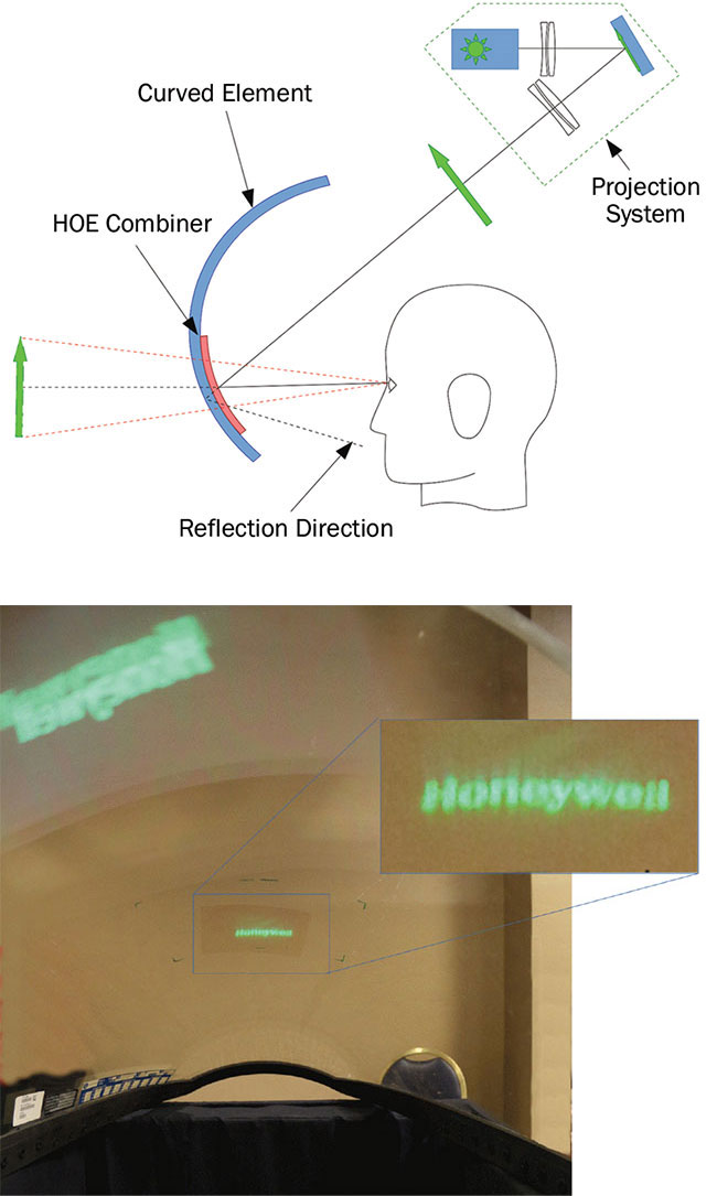
Figure 3. An example of an HOE (holographic optical element) combiner on a curved surface. Principle of action (top). HOE affixed on an F-16 jet fighter front canopy that presents an extreme curvature (bottom). The projected image is not distorted when diffracted by the HOE (inset), while it is significantly deformed, inverted, and duplicated when reflected by the bare canopy (upper left, photo). Courtesy of Pierre-Alexandre Blanche.
It is desirable to have the combiner reflect narrow wavelengths tuned on the projector source bands. Volume HOEs, which are recorded with an interferometric setup, act naturally as notch filters that are diffracting the same wavelength as the laser used to record them. By using three lasers of different colors — red, green, and blue — to record the HOE, it is possible to obtain a system that has narrow peak reflectivity in the center wavelengths of the red, green, and blue diodes and reproduce colors.
HOE for larger FOV
The FOV of an HUD or an AR system is a particularly important metric since it is related to the size of the image the viewer will perceive. While it is somewhat surprising to people entering the field of combiners that it is possible to generate a large image with a relatively small projection system when a scattering surface (screen) is used, it is much more difficult to do the same with a combiner. For now, HUD and AR systems are still generating relatively small images in comparison.
The small image size is due to the fact that a combiner is not a scattering surface, so it does not act as a screen. If a person were to face a conference room projector, for example, and look directly at it, no image could be seen, just an intense light spot created by the projector. This means the projection system for an HUD/AR system is fundamentally different from the projection system for a theater or a conference room.
In the case of an HUD/AR, the diffuser (screen) is located inside the projection system, and it is then imaged by the relay optics and ultimately redirected by the combiner (Figure 1). The consequence, then, is that the maximum possible FOV is directly proportional to the size of the relay optics. Or more accurately, the size of the last of the optical elements is divided by its distance to the viewer.
To maximize the FOV of an HUD/AR system, lenses nearly as large as the image created are needed in the projection system. But oftentimes, this is not desired or even possible because of constraints of space and weight: No one wants to wear a heavy pair of AR glasses or to have bulky optics protruding from their car dashboard.
HOEs can help in that regard since they can act as lenses. In this case, the HOE can be the final optical element of the relay optical train, located closer to the viewer than any other optical element, and can be much larger without being bulky. Both of these functions help increase the FOV of the HUD/AR system.
This can be appreciated by looking at a ray tracing of a projection system (Figure 4). The size of the last optical element essentially defines the FOV. If this element is a refractive lens, there is no room for a combiner. If this element is an HOE combiner, the system can perform adequately.
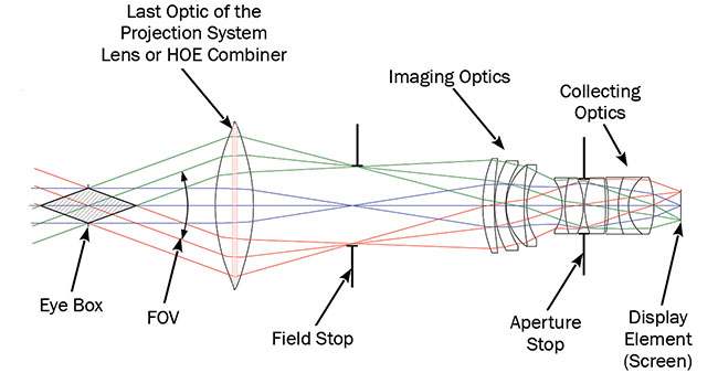
Figure 4. Ray tracing of a projection system for an HUD/AR. The size of the last optical element defines the FOV (field of view). This element is either a lens or an HOE combiner. Note: For the sake of clarity, the reflection function of the HOE combiner is not shown. Courtesy of Pierre-Alexandre Blanche.
Waveguide for large eye box
The eye box is defined as the region in space where the viewer can see the full extent of the image projected by the optical system. A large eye box offers better visual comfort since the viewer can move around without losing sight of the image. Conversely, a small eye box gives the viewer unpleasant tunnel vision.
In the case of the system shown in Figure 4, the eye box is relatively small compared to the size of the combiner. To improve upon this design, current systems use a waveguide approach that recirculates the light and multiplies the size of the eye box (Figure 5).
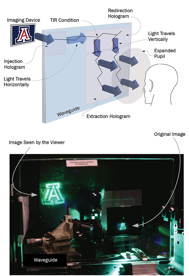
Figure 5. Principle of action of a 2D expansion waveguide combiner (top). Picture of a prototype (bottom). In the prototype, the image is injected by an HOE on the lower right, travels inside the waveguide from right to left at first, and then is redirected upward by a second HOE. Finally, the image is extracted by a third HOE on the upper left part of the waveguide. In this particular case, in addition to the pupil being expanded, the image is also magnified thanks to optical power provided by the injection hologram. TIR: total internal reflection. Courtesy of Pierre-Alexandre Blanche.
In this system, the light from an imaging device is injected inside a waveguide (a slab of glass with parallel faces) using a first HOE. A prism can also be used for this function. This injection element redirects the light at total internal reflection (TIR) so it propagates horizontally inside the waveguide. The light is then redirected vertically by another HOE that changes the direction of propagation while keeping the light inside the waveguide.
It is important to note that this HOE does not redirect all the light at once. Instead, it has a low efficiency that allows for some of the light to continue along its initial direction and interact multiple times with the redirection HOE. These multiple interactions extend the eye box horizontally by replicating the pupil of the system. Ultimately, the light is extracted from the waveguide by a third HOE, which also has low efficiency, to expand the pupil vertically.
In this system, the pupil is replicated a number of times, enlarging the eye box by the same factor. For this system to work, the beam extracted from the waveguide should be collimated, projecting the image at infinity. In this case only, the eye box is enlarged instead of the image being replicated several times. Fortunately,
far-field projection is often desired in HUD/AR systems.
Since the extraction HOE is designed to only interact with the light traveling inside the waveguide and has a low diffraction efficiency, the light from the outside world can pass through, making this system a very good combiner.
Next-generation combiners
Multiple developments are on the way
to further improve the next generation of HUD/AR combiners. So far, the FOV of waveguide-based systems seems to be limited by the minimum angle of propagation at TIR (42° in regular glass). Experiments have shown that using a higher-refractive-index glass increases the FOV. This solution, however, offers only a marginal improvement since the index cannot be increased by a large factor.
Another possibility for improving the FOV would be to use multiple waveguides,
each carrying the beams covering differ-
ent sections of the FOV, say 0° to 40°, 40° to 80°, and 80° to 120°. This approach could deliver multiple times the FOV of a single waveguide, and potentially cover the entire 150° of human vision.
Finally, curved waveguides would be more attractive to use for AR glasses than the current flat waveguide combiner. Curved waveguides, however, add the difficulty that the light propagating inside suffers aberrations because of the shape of the surface onto which they reflect. A possible approach would be to use predistortion optics, or to include this predistortion directly into the HOEs interacting with the light.
This research should lead to combiners that are light and efficient, and that integrate seamlessly to the environment, providing large FOV and comfortable eye box for both high-end HUD and AR systems.
Meet the author
Pierre-Alexandre Blanche, Ph.D., is a research professor at the College of Optical Sciences at the University of Arizona. His fields of interest are diffraction optics and holography; email: [email protected].