When galvo and stage elements are combined, lasers can streamline processes while ensuring quality of output.
CLIFF JOLLIFFE, PHYSIK INSTRUMENTE (PI) GMBH & CO. KG
Lasers are used in many industrial sectors for a wide variety of processes, including drilling, cutting, welding, and scribing, to optimize manufacturing and ensure high-quality components. Prices have fallen and, with the added application support offered by laser manufacturers, lasers are now being considered for use in areas where previously the risk of doing so would have been regarded as prohibitive.
One challenge for automation machine builders who want to introduce laser processing into their applications is how to strike a balance between precision, quality, and high throughput. Meeting this challenge requires motion systems capable of achieving exceptional levels of laser control by using fast, reliable automation networks, resulting in the merging of traditional programmable logic controller-based automation systems with high-performance motion controllers. The latest generation of these systems offers more flexibility, including simultaneous control of servo-based stages and galvanometer scanners (galvos), without the user needing to be a laser or automation expert.
The ideal approach to embedding lasers into a manufacturing process is to use modular products — for example, sensors, I/O boards, pneumatics, and motion axes — with industrial automation control networks, such as EtherCAT. The choice of such components is dictated by many factors, including the laser process itself, the material, the work cycle, and the ambient conditions, plus criteria such as throughput, precision, geometric tolerances, contours, and the size of the machining surface. Each application makes different demands and brings unique challenges.
Lasers, targets move together
Historically, manufacturing systems have relied on stepper and servo motor-driven mechanics that move the target object or material into the field of view (FOV) of the laser. This setup can produce good precision and adequate speed, but as demands on manufacturing throughput increase and feature size reduces — for example, in microhole drilling and cutting — higher acceleration with the same precision is required from the motion system. The acceleration performance becomes limited by the mass of the stages used in the motion system. Higher accelerations require more force from the motor and more force needs more current. This, in turn, generates heat from the motors, which can potentially have an effect on the system’s precision.
One way to overcome acceleration limitations is to incorporate a galvo — a dual axis, servo-controlled set of mirrors that directs the laser path. These devices can be used to achieve rapid acceleration and motion with low inertia, but they are limited by their FOV, which is often no more than a 100 × 100 sq mm. And, until recently, they have offered limited accuracy. However, scanner technology has improved, and galvos can now be relied upon to be at least as accurate as the stages. The process is no longer limited by the mechanics of the motion system but by the control system operation.
Combining galvos with servo-based stages increases the area that can be accessed by the laser, offering an EFOV (extended field of view), but the differing principles and requirements of these systems mean that control of a galvo is typically isolated from the controls for the corresponding motion stage. As a result, the two platforms generally work together in a stepwise manner — often described as “step and scan” — in which the stage moves the scribing surface to the center of the galvo’s FOV and control transfers from the motion system to the galvo. However, this handshake approach, and the fact that the motion system is stationary, has drawbacks. The start and stop nature of the process — as well as the difficulty in controlling two systems founded on different principles — is clearly inefficient and restricts throughput. In addition, close examination of materials machined using this process reveals breaks or stitching errors at junctions where scanning has had to be carried out in separate steps.
This problem becomes more apparent when the beam is operated near the fringes of the FOV. The application of correction algorithms enables an increase in the working range of the galvo, improving the precision of such systems over the complete working field. However, strategies are needed to increase the working area to avoid disruption in the features that lie across the perimeters of the galvo FOV. Studies have been undertaken to measure, predict, and correct for these errors. An example of this predictive correction is the vision system in use at the Fraunhofer Institute for Material and Beam Technology IWS in Dresden, Germany.
A newer technique involves simultaneously moving the scanner and the servo motion system. The implementation of continuous motion eliminates breaks in the motion path and, therefore, any stitching errors. Some technologies create a feedback loop between the scanner and the motion platform that allows the scanner to detect and actively compensate for errors being produced by the stage movement. However, this approach still leads to inaccuracies because an inevitable delay occurs between the scanner detecting the error that follows from the stages and the need to correct for it. In very high-speed motion — a few meters per second or more — the errors caused by this type of control system could be in the region of tens of microns, which is quite significant, especially for applications such as small-bore laser drilling.
Interest is growing in the development of control systems that combine high-speed laser galvos and larger motion platforms into a single controller interface, making laser machining a seamless process. These systems effectively overlay the small FOV of the scanner with the longer travel of the stage to provide continuous scanning. This approach goes a step further than other strategies, allowing true on-the-fly 2D processing. In practice, it offers far better performance — particularly in precision path errors — and can markedly increase throughput. Figure 1 shows an example of this kind of advanced system.
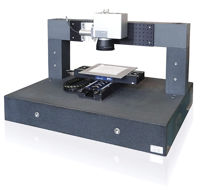
Figure 1. A motion solution that combines a high-speed laser galvo scanner and larger motion platforms into a single controller interface, making laser machining a far more flexible, seamless process. Courtesy of PI (Physik Instrumente).
Smooth process for LED screens
Glass cut with traditional machining methods can be prone to chipping and cracking. Laser processing, with its inherent noncontact method, is ideal for cutting the new generation of thin and ultrathin types of glass. When the process is correctly carried out, it is possible to cut specialized shapes that have fine edges. Process uniformity and the absence of errors is more important in some applications than others. When cutting large glass areas like LED screens, it’s important not to introduce any fine breaks or small cracks around the edges of the glass. However, a step-and-scan process to move the glass to the galvo operational area in a piecewise manner can be risky when the boundaries of the galvo areas meet, resulting in either increased optical distortion around the extremities of the galvo lens objective or misalignments between the motion stage coordinate system and that of the galvo. This may create weak points that can lead to breakages. Additionally, the laser is effectively switched off when the stage is moving and the galvo is stationary. Merging the movements of the galvo with those of the stage prevents this line discontinuity — the continuous scanning field offers a smoother process, reducing the risk of damage — and can improve throughput (Figure 2).
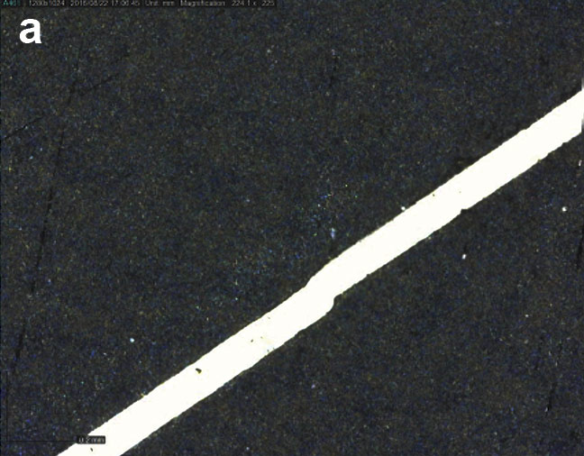
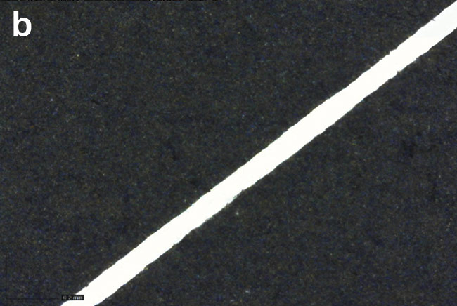
Figure 2. The step-and-scan approach with stitching errors at the boundaries (a). The EFOV solution showing elimination of
stitching errors (b). Courtesy of SCANLAB.
This continuity is important for applications such as OLED (organic light-emitting diode) technology, which is increasing in popularity and makes use of much thinner glass. The OLED manufacturing process involves a two-layer method and requires a high level of precision to seal the glass.
Smaller holes made more quickly
Another application for which combined control could be advantageous is drilling of ceramic substrates used as heat sinks. The average high-brightness LED converts only ~45% of the input energy into visible photons. The rest comes out as heat, which must be removed quickly to prevent potentially catastrophic overheating. Ceramic substrates are frequently used for this application, as there is an abundant supply of them and they are relatively cheap to produce. Their thermal management capabilities can be further improved by drilling narrow bore holes in very high densities to increase surface area and heat conduction. These holes can be created by mechanical punching or, preferably, laser drilling, which creates smaller holes and produces more consistent and circular apertures.
Until recently, a linear, motor-based planar mechanical bearing stage would have been considered ideal for this kind of application, offering exceptional geometric performance and using cross roller bearings to ensure smooth running and low friction. This results in accurate, fast, and consistent holes, but the gain in throughput of these systems is limited. Adding a galvo and synchronized control system to this setup would increase acceleration — and hence throughput — and offer the additional ability to produce smaller holes without creating errors.
Microvias and PCBs connect dots
A similar application is laser drilling of microvias in electronic components. Multilayer PCBs (printed circuit boards) require high throughput and accurate production of through and blind holes to establish an electrical connection between their various layers. Holes larger than
200 µm are normally created using mechanical methods, but manufacturing trends are demanding higher densities of smaller holes with diameters down to
25 µm. Lasers are efficient at drilling holes of this size through layers of copper and other common materials, such as epoxy resin and glass fibers. The problem is that the smaller the hole, the faster the acceleration needed to produce the circle. This is problematic when using only a large linear stage, because its mass and inertia will generate large following errors during the acceleration.
Using a combination of galvo and stages, however, works well. The stages offer the large area coverage that is required for processing, and the galvo achieves the high acceleration motion profiles for smaller holes. The recently developed EFOV techniques that merge the processing area of the stages with the FOV of the galvo significantly reduce the off-time of the laser when waiting for the linear stages to move into position, which increases throughput. Some of these systems offer additional advanced features that remove the time lag — which is commonly found on 2D-processing, on-the-fly arrangements — where the galvo attempts to correct for stage tracking errors. A strategy that attempts to maintain the laser spot closer to the center of the galvo’s FOV will improve accuracy and achieve consistent roundness of holes over large PCB areas. Figure 3 shows a representation of a PCB via drilling system.
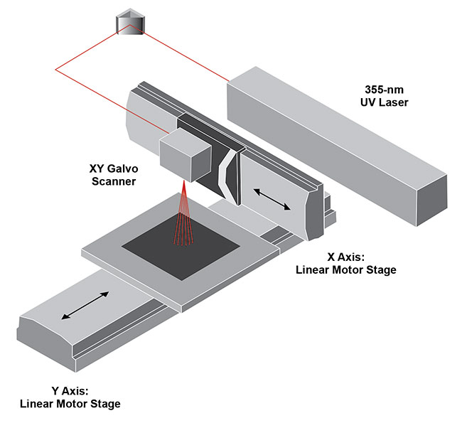
Figure 3. The PCBs are placed on a fast linear axis on the machine base, while the processing tool is arranged on another linear axis above the PCB axis. The image shows a UV-source laser with PI stages and a galvo scanner. Courtesy of PI (Physik Instrumente).
New world of wobble
In industrial processes, joining new materials can be challenging, especially when they are dissimilar and have different melting temperatures or varying reflectivity. Welding is the traditional answer when it comes to laser processing. Historically, systems have depended on technology with a large laser spot size that could be defocused to get a relatively thick weld of about a millimeter. Now, machine builders have started shifting toward fiber lasers that are cheaper, more robust, and more reliable but have a much smaller spot size — by a factor of 10 — which equates to a relatively thin weld line.
This problem is being overcome by using a galvo to introduce a wobble motion that overlays the standard motion path. Not only does this method produce welds of a few millimeters, but it also opens up a whole new realm of possibilities for welding effects, creating other motion paths on top of the weld. Wobbling the laser beam adds control over what is called a “keyhole” melt during the welding process. The keyhole melt is where the laser vaporizes the material and creates a keyhole that allows the laser to penetrate deeper into the material. By using wobble, it is possible to take advantage of the higher potential welding speeds of the fiber laser and benefit from the significant process control that affects the properties of the weld — such as penetration depth, weld speed, and weld width — as it is being processed. Control of the beam using a wobble method can produce fewer pores, less spattering, and higher cut and weld quality (Figure 4).
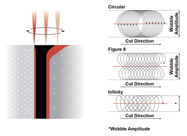
Figure 4. Keyhole melt welding using various high-speed wobble motions. Courtesy of PI (Physik Instrumente).
Independent control of the amplitude and frequency of the oscillation is normally achieved through the galvo mirror controller, allowing flexibility during the welding process, with typical frequencies up to 300 Hz used in most applications. The simplest example of this is using a circular motion of the laser spot, which allows a constant overlapping speed rather than a nonconstant perpendicular motion that can lead to overpenetration in terms of depth. Even better efficiency is provided by a figure eight or infinity shape, which gives much better energy distribution across the weld (Figure 5). Here the figure eight has its orientation rotation aligned with the direction of the motion stages.
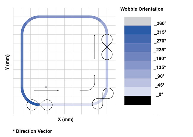
Figure 5. A wobble pattern tracks the system’s motion path. Courtesy of PI (Physik Instrumente).
Laser processes aim to meet demands
New challenges are emerging where frequencies greatly exceed those normally required in specific processes. For example, the automotive industry was an early adopter of laser welding, but the industry is now facing new tasks in electric vehicle manufacture, including that of joining copper to aluminum in battery technologies. Electrical conductivity and heat transfer improvements are desirable features after welding; however, normal techniques generally fail when joining aluminum and copper because they create very brittle intermetallic interactions.
Avoiding these interactions would improve the chances of a successful weld, and this has been attempted using a high-frequency beam oscillation and lateral beam displacement to vary the mixing ratio in the weld. A high-frequency wobble of >2 kHz can produce suitable mixed weld zones with reduced cracking and good strength. However, the high frequency can lead to failure of traditional bearing-based galvo systems. New developments rely on piezo actuators as the drive principle for high-frequency beam deflection systems. The high resonant frequencies, stiffness of the mechanical design, and friction-free motion of these tip/tilt systems (Figure 6) enable them to achieve the 2-kHz target and beyond.
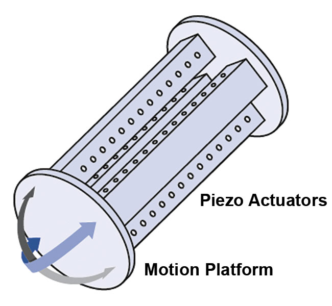
Figure 6. The tip/tilt system for high-frequency beam deflection is based on a parallel kinematic design with a single movable platform for the tip/tilt motion.
The platform on which the mirror is mounted is driven by piezo actuators. Courtesy of PI (Physik Instrumente).
Lasers can offer unmatched accuracy in a number of applications. The goal for a laser machine builder is to create a highly accurate system that meets the process requirements and includes throughput and accuracy that are highly dependent on the motion system. This has to be achievable in industry as well as in the safe lab environment. Each application has its own restrictions, but a system that simultaneously controls both galvo and stage elements offers flexibility for the current and future automation needs of laser processing.
Meet the author
Cliff Jolliffe, Ph.D., is head of precision automation and laser machining at Physik Instrumente (PI) GmbH & Co. KG. He nurtures PI’s business in precision industrial automation, investigating trends and listening to customer demands, then using this information to influence the company’s product development and sales strategies. Jolliffe has over 25 years of experience in the automation market, working specifically in the field of precision mechatronics for the last 18 years, including key roles in laser micromachining, medical device manufacture, and motion controller applications.