3D inspection provides improved resolution over 2D systems, as well as the ability to handle materials that are more difficult to image, thus enabling higher levels of quality control.
MATTIAS JOHANNESSON, SICK AG
Spurred by technological advancements, 3D vision has in recent years moved into the mainstream of automation. The benefits of 3D are increasingly in demand and, as a consequence, the number of vendors offering it has grown dramatically, while the performance capabilities of automation systems have increased tenfold over the last decade.
In the electronics industry, these improvements in speed and resolution have been crucial. The trend toward miniaturization has driven down the size of the components, and hence the size of the features to inspect. The dimensions of the smallest features have decreased by more than half over the last decade. In other words, 4× more pixels per square centimeter are required to maintain the same performance. At the same time, panel size is expanding, meaning there is more area to inspect. Concurrent with this, the industry is pushing to boost production capacity by increasing line takt. The required vision system bandwidth, measured as number of acquired and processed pixels per amount of time, has therefore grown by more than one order of magnitude over the past 10 years.
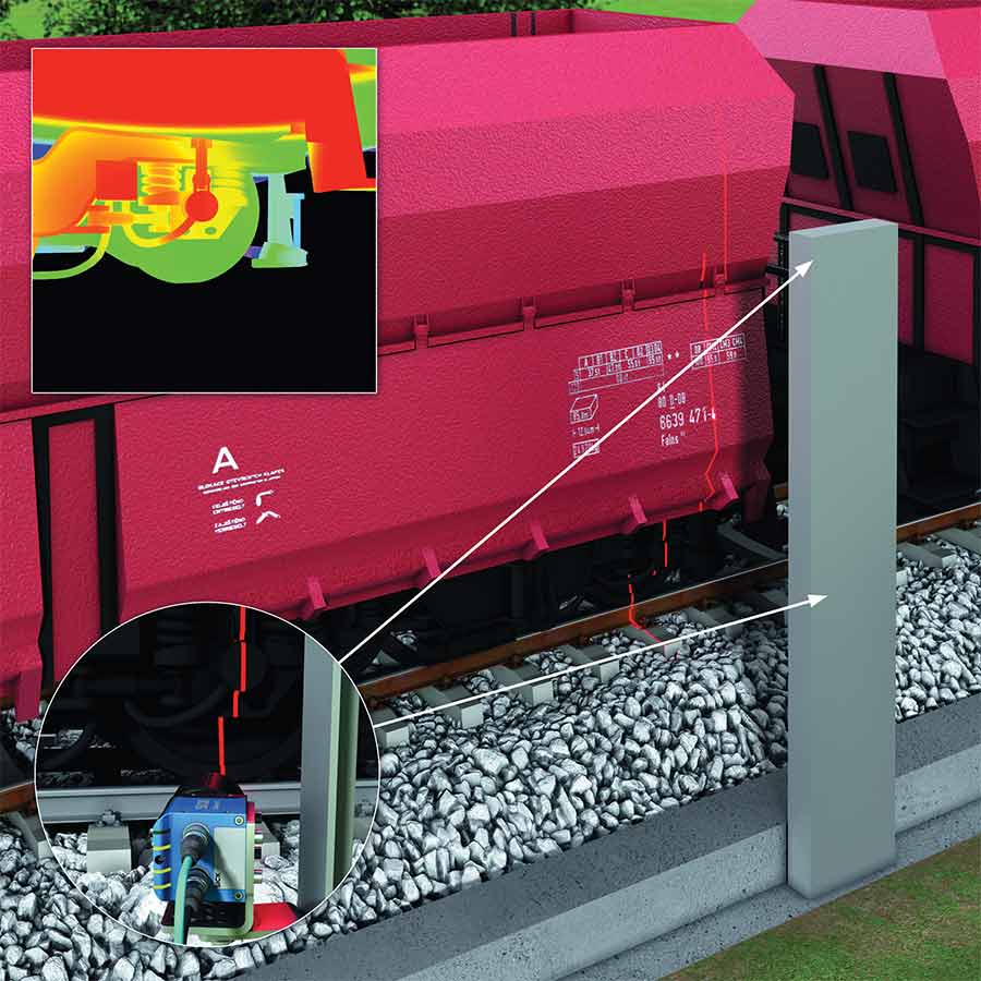
Figure 1. Laser line triangulation used to scan passing trains in predictive maintenance. The inset illustration shows how the laser reflects the profile of the train.
The industry overall requires higher levels of quality control on a wider variety of objects, creating the need for higher resolution, as well as the ability to handle materials that are more difficult to image. For many of these applications, in-line 3D inspection outperforms traditional 2D technology. Features such as connector pins and milk carton screw caps can easily be separated from the background and can be verified in shape and position, independently of color and contrast. Hence, 3D systems can in many instances provide more reliable results than 2D on items with varying characteristics.
The challenge of simplicity
Simplicity and ease of use become more important to 3D vision systems integrators. Beginning with the installation, often precious little space is available when adding machine vision to a production line. Most 3D systems need a dedicated light source located in a specific place relative to the camera, which adds bulk. A device with an integrated light source is easier to install than two separate units (a camera and light source). Conversely, separating the light source and camera allows greater flexibility to adapt to the requirements of a specific application. If the 3D camera comes without precalibration, then it is also essential to acquire supporting
software and calibration targets.
For a systems integrator using cameras, software adaptation can be a challenge because, historically, vendors have implemented their own custom protocols, data formats, and software interfaces, making each solution unique. The work required to standardize transport layer protocols and software interfaces for machine vision has now reached a mature state that also encompasses 3D. The configuration
and data formats needed for 3D systems are typically more complex than those needed for 2D cameras. It is common for the 3D camera to deliver range (distance), reflectance (brightness), and confidence data all from the same point.
The industry requires higher levels of quality control on a wider variety of objects, creating the need for higher resolution as well as the ability to handle materials that are more difficult to image. For many of these applications, in-line 3D inspection outperforms traditional 2D technology.
GigE Vision now has a transport layer capable of handling the complexity of 3D camera data. And GenICam standards provide a transport-layer-independent application programming interface (API) capable of complex 3D data transfer, as well as standardized software features. Many vendors within the machine vision community actively work with standards developers and have products certified according to
the resulting standards.
A 3D camera that delivers high-quality data out of the box, without needing parameter tuning by a vision expert, is another example of the trend toward simplicity. Using a sensor with high dynamic range (HDR) is vital to providing good data under varying circumstances — for example, shiny, bright component legs on a dull, dark substrate. Many HDR imaging methods are available, such as nonlinear multi-slope analog-to-digital conversion, and multiple exposures are available and are now seen in state-of-the-art laser triangulation systems.
In some applications, the laser reflects off the main target (if it has a metallic surface, for example), strikes another part of the scene, and reflects back to the camera, thus creating a problem. This results in multiple peaks on the imager column, instead
of the expected single peak. If the
camera can detect multiple peaks, this
information can be passed up the
signal processing chain — to image
processing — to construct the most
likely true shape.
Polarization offers another method for obtaining high-quality data when working with metallic surfaces. A laser can be linear, while another linear polarizer can be used on the receiver side to
admit only a certain polarization direction. Given that metallic surfaces
change the light polarization in a deterministic way, it then becomes possible to separate the direct reflection from the secondary. The Keyence LJ 7000 family of laser triangulation sensors, for example, incorporates technology with polarization to reduce secondary reflection problems.
Laser triangulation
With sheet-of-light triangulation at each instance in time, a cross section of the scene is measured to create a height profile (Figures 1 and 2). Many
industrial applications include linear motion, as in the case of an object passing along a conveyor. A camera measuring cross sections can create
complete height maps of the objects as
they pass the laser line. In these types
of applications, laser line triangulation
is often the most suitable 3D imaging
technology.

Figure 2. An illustration of laser triangulation. A camera views the laser line and extracts 3D profiles of passing objects.
Laser line triangulation uses a 2D image sensor, and it is therefore vital to extract, rapidly and with high precision, the position of the laser line on each column of the imager. This provides a profile of data that depicts the shape of the object. It is typical to also extract the brightness of the seen laser to provide 2D intensity (reflectance) data.
Additional measurements of the reflected profile shape can provide information about important material
properties.
All triangulation systems need a
baseline distance between light source
and sensor. This creates the necessary
base for the measurement triangle, with
its corners placed at the laser origin,
the optical center of the camera, and at
a point on the target. In general, a large
baseline provides higher measurement
precision.
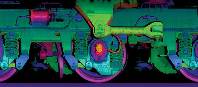
Figure 3. Predictive maintenance of trains that pass at speeds up to 120 mph (200 kmh) requires scanning in 46 KHz to reach 1 scan/mm. 3D data helps locate any out-of-place objects. The false coloring is made using the depth map data as hue information.
The base distance needed for triangulation creates occlusion problems, however, where the light source does not illuminate areas seen by the camera, and vice versa (Figure 3). This gives edges to areas around large objects — where it is not possible to measure, for example. The larger the baseline, the more occlusion. If the sensor itself works with high precision, the baseline distance can be small, but typically, an angle of at least 20° to 30° is used between the light source direction and the viewing. To overcome occlusion effects, multiple light sources and multiple cameras can be used (Figures 4 and 5). Frequently, multiple cameras are also used to increase the measurement field of view (FOV) and create 360° profiles around target objects.
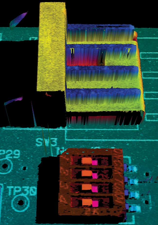
Figure 4. Laser triangulation causes occlusion and, therefore, regions with missing data.
Scheimpflug-optimized focus
One key to high-quality imaging is the sharpness of the image data. A lens has a limited depth of focus, which can create problems in 3D systems in which the measurement range is large. For laser triangulation, the Scheimpflug
principle is useful. This principle
defines how to reach focus in front of
the camera on a specific tilted plane by initiating a precise tilt of the sensor behind the lens. In laser triangulation, by tilting the imager behind the lens, the measurement (laser) plane can be focused perfectly. This creates optimal
focus even when using a large lens
aperture to capture more light. Most laser triangulation products with built-in
lasers and optics use this principle to create optimal conditions. Using the Scheimpflug principle is more complex if starting with a separate laser and camera where the lens mount typically
is fixed. Some cameras aimed at triangulation have different adapters available so that suitable Scheimpflug
correction can be applied.
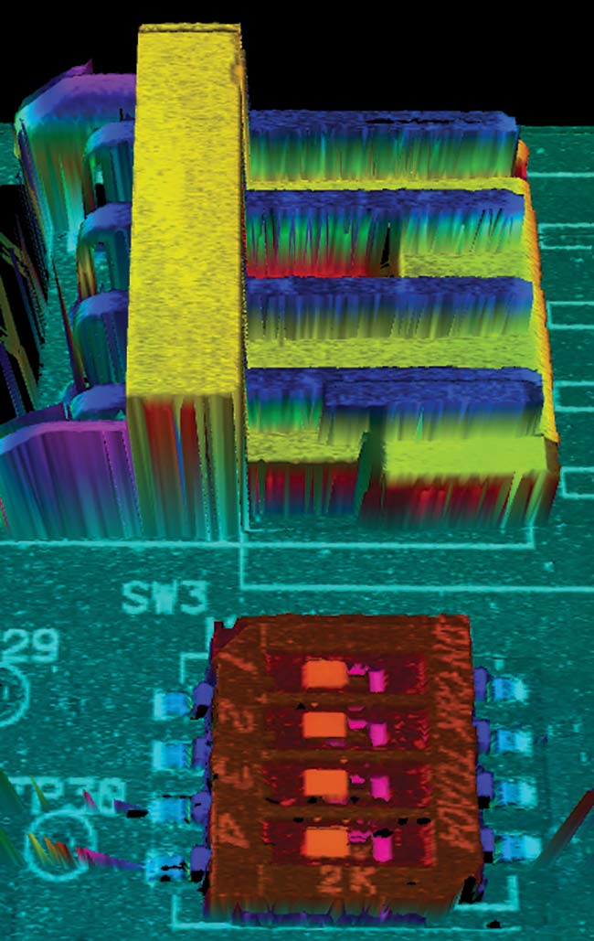
Figure 5. By using dual cameras imaging from various directions, occlusion is reduced, and the connectors on both sides of the dual in-line package (DIP) switch can be imaged and inspected.
Lasers, as suggested by the term “laser triangulation,” are the typical light source used in these systems, since they emit high-powered coherent light from a very small aperture. This light can be focused as a narrow and bright line. It also emits a very precise wavelength, and therefore narrow-bandwidth optical filters can be used on the camera to block disturbing ambient light. However, the downside of coherence is that speckles are created in the imaging system. Speckles are interference effects of coherent light photons that travel slightly different distances from the source to the sensor. They strike
an uneven surface and pass through
a lens aperture before reaching the
imager, causing interference patterns that are bright if the distances “add up” to whole wavelengths, and darker if they do not. This creates speckle noise and can impair the extraction of the
position of the laser. Laser speckle size on an image sensor is proportional to the wavelength, everything else being constant. The speckle size is also
roughly proportional to the lens aperture f number. Thus, a larger aperture (smaller f number) generates smaller speckles. The more speckles that fit onto a single pixel, the more averaging
of the speckles, and thus the lower the
noise. Advancements in imager technology lead to smaller pixels, which aggravates the issue of speckles; thus the smallest pixels should be avoided. Since speckle size is proportional to wavelength, blue lasers — rather than red or IR lasers — typically provide
better data quality (Figures 6 and 7).
A Scheimpflug-corrected optical system using a large aperture is helpful for reducing laser speckle noise, as well as for providing more light to the imager.
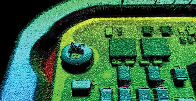
Figure 6. 3D data from a PCB with components scanned by a red 660-nm laser. Speckle-related noise is clearly visible as 'orange peel' effects. The large components measure 3 X 3 mm with a thickness of 1 mm.
The laser triangulation principle provides large scalability. It allows for the imaging of anything from solder paste and small components with a FOV of a few millimeters, for example, to imaging whole trucks and trains with meters of length in the FOV.
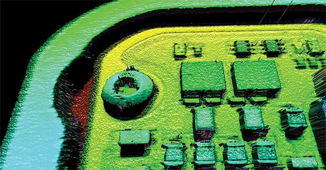
Figure 7. 3D data from a PCB with components scanned by a blue 405-nm laser. The speckle-related ‘orange peel’ noise is much lower in amplitude than with the red laser.
On-chip data reduction
Throughput at the imager side — to be able to produce as many 3D profile points per second as possible — is critical to reaching high performance in laser triangulation. For each exposure, N × M sensor pixels are reduced to the M range and possibly to reflectance values. Performing the reduction on-chip greatly reduces post-processing demands, and also makes it possible
to achieve higher performance in a smaller and less power-hungry camera. State-of-the-art, high-speed imagers from special suppliers such as Luxima and ams/CMOSIS reach medium
speed but load the FPGA/CPU with
very high data rates.
As an example, the high-performance
LUX13HS sensor from Luxima reaches 4 KHz at 1280- × 720-pixel resolution, using 64 high-speed LVDS (low-voltage differential signaling) outputs totaling 27.5 Gb/s. At a typical triangulation
FOV using 256 rows, the corresponding speed is 11 KHz. The M30 imager
with on-chip data reduction used in
the Ranger3 family of laser triangulation cameras from SICK reaches over 23 KHz at 2560- × 256-pixel resolution with an output bandwidth of less than 4.5 Gb/s. That is, the processed pixel
throughput is doubled in resolution (2560 vs. 1280 columns) and more than
doubled in frequency (23 vs. 11 KHz). The result is more than 4× higher
performance (in processed 8-bit pixels per second) with an output bandwidth
of less than 20%. The data rate reduction makes it possible to process the
data using fewer resources and less power. Another example of a custom imager for laser triangulation is in the Cognex DSMax, which reaches 18 KHz with 2000 points per profile. Both of
these imagers have state-of-the-art HDR (high dynamic range) imaging
support and other advanced features
that facilitate obtaining good data from
difficult scenes.
Using standard imagers, a very low number of rows (N) are typically needed to reach these high profiling speeds, but this reduces the possible depth of
field or alternatively provides poor resolution if using a very small baseline.
Laser triangulation is a robust and well-proven 3D-imaging method that is well suited to today’s industrial inspection tasks. The main technological challenge for industrial laser triangulation has always been the need for high-speed imaging and data reduction near the sensor. Vendors have successfully leveraged full custom CMOS imagers for this application for more than 25 years. CMOS imaging is evolving further, and technologies such as flip chip and 3D stacking are now viable. These kinds of technologies make it possible to achieve even more compact, lower-power (yet
faster), more sensitive, and more complex front ends for 3D imaging, making it likely that laser line triangulation technology has a very bright future.
Meet the author
Mattias Johannesson is a senior expert in 3D vision within the research and development department at SICK. He has more than 25 years of experience with 3D cameras and full-custom CMOS image sensor development. Johannesson currently works at the Competence Center for Machine Vision at SICK IVP in Linköping Sweden; email: [email protected].
Quantum dots are tuned to build IR cameras cheaply, efficiently
To build an inexpensive IR camera, scientists at the University of Chicago leveraged the wide spectral tunability of colloidal quantum dots (CQDs), tweaking the CQDs to develop a formula to detect shortwave IR and another formula to detect midwave IR.
The researchers developed a two-terminal CQD dual-band detector that provided a bias-switchable spectral response in two distinct bands. By controlling the bias polarity and magnitude, the detector can be rapidly switched between shortwave and midwave IR at modulation frequencies up to 100 kHz. The detector performance was demonstrated by dual-band IR imaging and remote temperature monitoring.
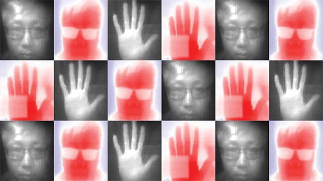
Photos taken by researchers testing a new method to make an IR camera that could be much less expensive to manufacture. Courtesy of SICK AG.
The tunability of the CQDs enables them to pick up different parts of the IR spectrum. “Collecting multiple wavelengths within the infrared gives you more spectral information. It’s like adding color to black-and-white TV,” researcher Xin Tang said. “Shortwave gives you textural and chemical composition information; midwave gives you temperature.”
The resulting camera performs well and is much easier to produce than traditional IR cameras, the researchers said. There are many potential uses for inexpensive IR cameras, including in autonomous vehicles, which rely on sensors to scan the road and surroundings. Today’s IR cameras are made by successively laying down multiple layers of semiconductors, an expensive process that prohibits their use in most consumer electronics.
“Traditional methods to make infrared cameras are very expensive, both in materials and time, but this method is much faster and offers excellent performance,” Tang said.
The research was published in Nature Photonics (https://doi.org/10.1038/s41566-019-0362-1).
|