Dr. Artur Olszak and Mike Zecchino
The ability to scan for lateral defects and to collect 3-D height
data makes this technique attractive for high-speed precision inspection of wafers
and substrates in semiconductor, telecommunications and MEMS applications.
Semiconductor, data storage, optical telecommunications and microelectromechanical systems (MEMS)
applications often require surface measurement across relatively large areas with
nanometer resolution. With rising demand for smaller form factors and for more stringent
quality controls, there is a growing need for fast, precision metrology to characterize
surfaces as diverse as wafers, substrates and individual components.
White-light interferometry is an established tool
for high-speed determination of such three-dimensional surface shapes over areas
as large as the field of view of the instrument (typically up to 15 mm). However,
measurement speed drops dramatically for larger surfaces because the system must
stitch together data sets from several scans to form the image. One solution —
lateral-scanning interferometry — is a variant of the conventional technique.
To understand the new method, it helps to examine the traditional one.
White-light interferometry, or profiling,
works well on surfaces with average roughness down to 0.1 nm, peak-to-valley heights
reaching several millimeters and repeatability of 0.1 nm or better.1 The technique
is based on the detection of the coherence peak created by two interfering, polychromatic
wavefronts.
Measurement begins when the sample
surface is illuminated with a white light source and brought into focus. A beamsplitter
directs a portion of the beam to the test surface and the remainder to a reference
surface. Recombining the reflected beams forms a pattern of light and dark interference
fringes that can be projected onto a CCD camera and captured by analysis software.
At each point, the fringe intensity is strongest at the coherence plane, where the
optical path difference for that point is zero.
The inspection system can re-create
the sample surface by obtaining several frames of intensity information for each
point. This process requires translation of the surface so that all points of interest
are scanned through focus, with intensity frames acquired at known intervals. To
do so, conventional white-light systems translate the objective vertically along
the optical axis. In this arrangement, the system field of view defines the size
of the measured area.
Characterization of larger surfaces
involves gathering data that is representative of a number of regions and combining
that information to build a view of the entire surface.2 This stitching process
requires that the scanned regions overlap, so the overlapping data can be aligned
with adjacent measurements. Because the equipment measures overlap regions more
than once, overall measurement time increases. This extra time can become a critical
efficiency issue in high-volume production, particularly for larger parts like silicon
wafers or semiconductor panels.
One less stitch in time
Unlike conventional interferometers, a lateral-scanning
profiler has its optical axis and coherence plane tilted with respect to the normal
of the object surface (Figure 1). Object translation is lateral instead of vertical.
Because of the tilt in the coherence plane, each point of the object’s surface
intersects the plane at a different time, depending on the height of the surface.
Again, fringe intensity is used to determine the height for each point on the surface.
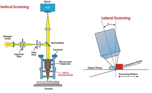
Figure 1. Unlike conventional interferometers,
a lateral-scanning profiler, right, can acquire long strips of 3-D surface information
at high resolution without requiring the stitching of data sets to form the surface.
Lateral scanning requires that all
the points on the test surface pass through the coherence plane. Therefore, the
system’s tilt and magnification limit the maximum measurable peak-to-valley
height, which still typically can be in the range of tens of microns. In addition,
the camera orientation is such that the system can follow points on the surface
along a pixel line during their advance through the field of view. Because the scan
speed and system magnification are known, it is possible to track each point between
consecutive frames. Using the scanning speed, the direction of travel and the modulation
of the acquired intensity, the system can reconstruct object surface topography.
The result is high-speed measurement of long data strips without stitching.
Lateral profiling not only eliminates
the need for stitching in one direction, but also measures at production-level speeds
with vertical resolution of less than 2 nm. The number of lines of the detector
and the tilt of the instrument with respect to the surface normal define the total
vertical measurement range. End users choose the scanning speed so that the object’s
motion in the camera plane across one frame of acquisition matches the pixel size
in the X direction. In this way, each point of the object moves one pixel between
frames.
For small magnifications, the pixel
spacing and required tilt also are relatively small. As the magnification increases,
the pixel spacing decreases and, therefore, the tilt of the instrument must increase.
Because the working distance of a higher-magnification objective also decreases,
the mechanical design of the objectives could quite possibly limit the magnification
with which lateral-scanning interferometry can function.
Put to the test
To test the capabilities of lateral-scanning interferometry,
engineers adapted a commercial optical profiler, the Wyko NT2000 from Veeco Instruments
Inc., to include a magnification range from 1.125x to 100x and motorized X-Y translation
and tip-tilt stages. The system’s coherence length was approximately 4 mm,
and the camera operated at 30 fps.
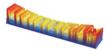
Figure 2. A lateral-scanning interferometer
created a profile mapof a magnetic head row bar with one scan pass in about 20 seconds.
The bar section measures 1 x 7 mm, with a total height variation of 8 mm. Depth
of the slider pattern is on the order of 6 mm. Conventional interferometry took
90 seconds and used seven stitched data sets to create the same map.
The full-speed advantage of lateral-scanning
interferometry can be realized in applications that involve measuring elongated
objects or a number of objects aligned along an axis, such as in the manufacture
of semiconductor laser diodes and other products processed in bar format. For instance,
in the production of magnetic recording heads, a wafer containing thousands of parts
must be sliced into row bars that are several dozen heads long by one head wide.
During processing, a bar must remain flat over its length so that subsequent etch
and deposition processes will be uniform across it. The overall bow of such bars
is often so large that stitching algorithms cannot accurately reproduce the surface
(Figure 2). Using lateral-scanning interferometry, the engineers measured a magnetic
recording head row bar in a single pass that took about 20 seconds. Measurement
time using the vertical-scanning technique took about 90 seconds and required seven
stitched data sets.
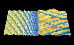
Figure 3. During high-speed inspection of two subsequent machining
operations on an aluminum block, lateral-scanning interferometry allowed engineers
to repeatably measure average roughness as low as 3 nm along long scans.
The speed advantage extends to flat
surfaces as well (Figure 3). In the high-speed inspection of two subsequent machining
operations on an aluminum block, lateral scanning enabled repeatable measurements
of average roughness as low as 3 nm over long scans.
The long-scan capabilities also translate
to nonplanar surfaces, such as those of a shaft, printer roll or other cylindrical
shape. Shaft manufacturers need to control runout, surface quality and defect levels
during production. By employing lateral scanning and a combination rotational/translational
stage, they can present the entire surface of a shaft to an objective for measurement
to produce a complete 3-D surface map. In addition, the system acquires only one
row of points at any time, so it can ignore overall cylindrical shape and record
only surface roughness (Figure 4).
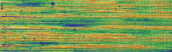
Figure 4. Combining lateral scanning with a rotational/translational
stage, manufacturers can present the entire surface of a cylindrical shaft to an
objective for measurement, leading to a complete 3-D surface map. In this case,
the system indicated an average roughness of 250 nm.
Some considerations
Lateral-scanning interferometry relies on the
accurate correlation of the signal from the camera pixels with the physical location
of a point on the object’s surface. Therefore, the tilt of the measurement
head and the scanning speed must remain stable over time. Both parameters also
require proper calibration. Miscalibration of the stage speed alone can cause contours
to “wash out” in the direction of scanning.
As with all interferometers, the lateral-scanning
technique is susceptible to vibration and resonance frequencies. However, where
vertical-scanning systems require vertical motion of the object or scanning head,
a lateral-scanning mechanism can employ a more rigid, stationary frame with simple
focusing motion, which simplifies its physical design.
The lateral-scanning technique’s
vertical-scanning range also correlates with the resolution of the CCD detector
along the scanning direction. Users can extend range with a larger CCD camera, but
the acquisition rate will be slower. One solution is to use an oversampling procedure
in which the images are acquired at intervals corresponding to 450°, for example.
By increasing the tilt of the instrument, one can introduce denser fringes in the
field of view to the point where 1 1/4 fringe would correspond to one pixel. This technique can extend the scanning range by a factor of five, but at the cost of some decrease in accuracy and repeatability. This arrangement also makes the system more susceptible to the object’s surface tilt.
Although white-light interferometry
remains a competitive tool for many measurement applications, lateral-scanning interferometry
can acquire long strips of 3-D surface information relatively quickly while retaining
high resolution. The technique should prove useful in a variety of production
measurement applications, particularly those in which a single linear scan can characterize
the entire test surface. Measurement of difficult-to-handle items such as rolls,
shafts and discs also could benefit.
References
1. A.G. Olszak, J. Schmit and M.G. Heaton (2001).
Interferometry: Technology and applications. Veeco Instruments Inc., Tucson, Ariz.
2. J.C. Wyant and J. Schmit (1997).
Large field of view, high spatial resolution surface measurements. Proc. of the
7th Intl. Conference on Metrology and Properties of Engineering Surfaces, Chalmers
University of Technology, Göteborg, Sweden.
Meet the authors
Artur Olszak is a senior optical engineer at Veeco
Metrology Group in Tucson, Ariz.
Mike Zecchino is the marketing communications
manager at Veeco Metrology Group.