Ruggedizing the design of imaging equipment enables machine vision to work outside the lab.
Alexander Moy, Edmund Optics
Exploding beer bottles, tsunamis and flour may not seem to have anything in common, but they are all hazards that machine vision systems can face in field applications. System designs targeting the controlled conditions of a lab expect an ideal working environment, not real-world problems. When a system must be deployed outside the laboratory, less than favorable conditions make the design challenge formidable. Fortunately, there are options for dealing with harsh environments.
Unfavorable environments can vary widely, but generally they involve one or more conditions that can interfere with the performance of — or that even can damage — an imaging system. The most common are extreme temperatures, shock and vibration, and exposure to particulates such as dust and to fluids such as water. Examples abound.
In food and beverage processing and packaging, vision systems encounter particulates such as drifting flour, impact from containers that occasionally explode while being filled, and fluids from the periodic heavy wash down and cleaning of the food-handling equipment. In lumber processing, the hazards are vibration from equipment as well as the particulate sawdust. Early-warning weather systems operate in inclement weather that produces precipitation and temperature extremes. Outdoor inspection applications where cameras are mounted on cars face weather and vibration, and underwater applications are challenged by the presence of water and pressure.
An early approach to harsh environments was to treat the imaging hardware as disposable and to replace it once it no longer operated reliably. This approach usually precluded the use of high-performance components, however, because of their higher cost. Making the imaging hardware disposable thus often sacrificed image quality.
Another common option was to build custom enclosures to protect the imaging system hardware, a technique typically used when the replacement costs of disposable hardware were prohibitive. Although this option greatly improved protection, it also increased the size of the imaging system, making it nonviable for space-constrained applications. Enclosures also tend to degrade the optical performance because the added optical surface can deform the image, add unwanted reflections, introduce stray light and cause other illumination problems. What is more, tooling adds greatly to the expense of a custom enclosure system.
Neither solution is ideal, so camera and lens manufacturers are moving toward a third: developing machine vision components that can withstand the rigors of harsh environments. This approach reduces cost and maintenance time by eliminating the need to replace malfunctioning parts constantly or to build custom enclosures.
Building an imaging system to survive such harsh environments can be tricky. Each condition affects the system differently and requires designers to employ a variety of approaches tailored to the specific environment. Fortunately, to address each environmental challenge, there are a number of standard techniques from which designers can choose.
Temperature control
For most imaging applications, temperature challenges revolve around dissipation of the heat generated within the equipment. Field environments rarely are cold enough to interfere with the operation of the electronics; however, these easily become hot enough to cause equipment failure when there is inefficient or ineffective heat dissipation. Ideally, the electronics, especially the image sensor, should be kept below 50 °C.
Machine vision systems use the traditional methods for controlling heat in the electronics, including heat sinks and fans. High-energy applications involving lasers or installations in high-temperature environments may even require water cooling. The specific choice depends strongly on the installation.
Heat sinks are suitable for most applications, provided that space is available; however, they tend to be bulky and require a free air space around them for convection to occur. For image sensors, the camera body itself can be designed to serve as a heat sink.
Heat sinks can be used in conjunction with fans to improve dissipation, or fans alone may do the trick by circulating cool air through a system. To avoid particulate contamination, however, the fan will need a “clean” air supply, generally created by drawing air through a filter. The fan can be configured for intake, forcing cooler outside air into the enclosure, or for exhaust, expelling the hotter air from within the enclosure. In general, exhaust fans will wear faster, leading to earlier failure.
In some cases, the system may have to operate in an environment where the ambient air is too warm for adequate heat dissipation. Then the system may require alternative methods such as refrigeration or water-based cooling. It also may be possible to use thermoelectric cooling of specific components such as processors or the image sensor.
Vibration and shock
Vibration is the leading cause of a number of failures, including alteration of the imaging lens focus, unthreading of the lens from the camera, optical misalignment, and electronic equipment joint and connection failures. Shock also is present in many installations — particularly in machinery that is engaged in repetitive motion — and can have similar effects. Both are mitigated using similar techniques, the most common of which are the use of damping material, additional locking screws and thread-locking adhesives.
Damping material can be used in several ways. It can be placed at mounting points to reduce the transmission of shock and vibration from one unit to another. It also can be used within an enclosed space to restrict the motion of units within that space. For focusing lenses, special damping grease is available to make the focusing movement stiffer and less likely to move.
Locking screws help prevent the movement of optical system elements under shock and vibration. They can be particularly useful in systems that have a fixed focus or in one that must be changed only occasionally. A nylon-tipped set screw can hold against minor shock and vibration and has the advantage of not harming the focusing mechanism. Where more extreme conditions exist, a dog-point or cone-point set screw will hold better but will mar the moving parts and will cause the focus movement to become rougher. Such set screws are best used with lenses that do not need frequent refocusing.
Thread-locking adhesives help prevent screws and the like from loosening during vibration and can be used on virtually all such retainers. With lenses, there are very few screws to lock in place, but there are retaining rings that hold the lenses in the barrel. These rings also can use locking adhesives as long as care is taken not to allow excess adhesive to mar the lens.
Water and particulates
Exposure to water or other fluids can wreak havoc on an imaging system by causing short circuits in the electronics, resulting in equipment failure. Fluids also can harm lenses by damaging coatings or by creating condensation that can impair resolution and light transmission. Avoiding fluid damage depends on where the fluid comes from. For incident fluids such as rain, merely deflecting the fluid may be adequate protection. For submersion, pressure spray or high humidity, watertight seals may be required (Figure 1).
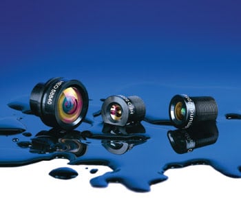
Figure 1. Making lenses waterproof requires seal and gasket materials — such as silicone — that offer low water permeability.
The two main methods for providing watertight seals are adhesives and gaskets. Adhesives, such as room-temperature vulcanizing adhesive and silicone, are relatively easy to apply and can be used in tight spaces but can have problems with consistency and workmanship. They also are inappropriate for junctions that may have to be dismantled periodically, such as the lens-to-camera mount connection. In such situations, gaskets must be used, although they can be difficult to incorporate into small spaces.
Gaskets involve less workmanship-related variability than adhesives. The most common form used in imaging systems is the silicone O-ring. Other materials may be used, but the material must have very little water permeability if it is to withstand deep immersion or high humidity. Any moisture that makes its way between the lenses of an imaging system can cause fogging and reduce visibility throughout.
Exposure to particulate matter in imaging systems has effects similar to those of fluid exposure: short circuits and obscuring of the optical path. Particulate buildup also can reduce the effectiveness of heat sinks and air cooling by adding an insulating layer and, if driven with enough force, can abrade the system’s exterior surfaces. Fortunately, the same methods used to prevent fluid intrusion into a system will keep out particulates.
One part of the imaging system that is difficult to protect from particulates, however, is the external surface of the lens. An optically flat barrier made of appropriate material can help provide abrasion resistance, but little can be done to prevent material from adhering to the surface and obscuring the optical path. The answer in such situations is to clean the outer surface periodically. This may require disassembly of the system to gain access to the lens’s surface, thus adding to system maintenance costs.
A new option in lens construction allows imaging systems to be cleaned with a pressure spray system. Making an imaging system pressure-cleanable is similar to making it waterproof with strong seals. Providing a mechanical means for diverting the pressure spray away from the seal to avoid direct stress will help ensure a stronger seal.
The advantage of this option is that pressure sprays are in common use for cleaning industrial equipment and vehicles. Having the imaging system pressure-cleanable thus can simplify maintenance after installation. It simply gets cleaned with the pressure wash at the same time as the rest of the equipment.
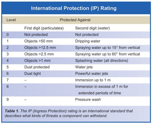 Pressure-cleanable lenses are becoming commercially available, eliminating the need for imaging system designers to create their own solutions. One such offering is the HEO (harsh environment optics) imaging lens series from Edmund Optics Inc. These lenses feature a unique watertight seal suitable for high-pressure wash-down applications. The design is based on IPX7 and IPX9K standards. International Protection (IP) standards (also called Ingress Protection standards) classify the level of protection that a part can provide against the incursion of foreign objects or materials, such as solids and liquids.
System designers selecting such lenses should examine the IP rating to make sure that the lens will tolerate the environmental conditions expected. The IP rating format consists of the letters “IP” followed by two numbers and, occasionally, an optional letter (Table 1). When no protection rating relates to a certain criteria, an “X” acts as the placeholder. The first number, ranging from zero to six, denotes the level of protection the assembly offers against ingress of solid particles. The second number, ranging from zero to eight, denotes the level of protection the assembly offers against the ingress of liquid. The liquid-ingress range recently has been extended to nine to include a rating for high-pressure, high-temperature wash-down applications. Achieving a rating of nine requires testing with a pressurized spray at a variety of angles (Figure 2).
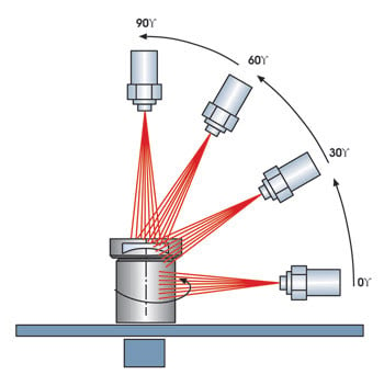
Figure 2. To certify a lens for pressure washing, it must be tested with sprays at a variety of angles.
Technology at work
With the advent of such ruggedized imaging products, harsh environment imaging is finding new applications. Machine vision has found successful deployment in food-packaging inspection as well as in crop harvesting machinery, industrial construction machinery such as dump trucks and cranes, consumer automotive guidance systems, unmanned robotic machinery, marine biology equipment and life sciences studies.
On a snack food-processing line, for instance, a harsh-environment imaging system is used in combination with a board-level camera to detect whether packages are sealed properly, replacing manual inspection. In operation, the camera sends an image of the package to a central processor that uses special algorithms to determine whether the package is sealed. The lens provides reliable image detection of packages through a cloud of flour and other particulates. In addition, the system can withstand high-pressure wash down at the end of each day to remove flour that collects on the equipment.
In a harvesting application, a camera/lens assembly mounted on a cornstalk chopper sends an image to an in-cab screen, providing the farmer with a clear view of the area around the 50-ft-long chopper, helping him to avoid hitting people or obstacles in the field. Use of the machine vision system greatly improves safety and efficiency compared with visual observation by the driver. The harsh-environment imaging system operates reliably in the dust, dirt, weather and temperature extremes of the farm environment, and it survives high-pressure wash down at the end of the day.
Harsh-environment imaging also has found a home on construction equipment to give the driver a clear view of the area in front of the machinery. These machines typically sit high off the ground, and the driver has difficulty seeing people and objects directly in front of the vehicle. The machine vision system sends an image to an in-cab monitor, helping the driver to avoid accidents. The lens provides a reliable image in the dusty atmospheres of a construction site, and it can survive heat, humidity and weather extremes as well as high-pressure wash down.
The key to all of these successful applications has been the design of the imaging system to tolerate the real-world conditions that laboratory equipment never sees. By accounting for heat, vibration, water and dust, designers are creating systems that can handle the worst that the field can throw at them.
Lens and camera providers are doing their part by providing ruggedized elements to give system designers the building blocks they need for handling harsh environments.
Meet the author
Alexander Moy is a product line engineer at Edmund Optics in Barrington, N.J.; e-mail: [email protected].