Backlit symbol inspection requires photometric capabilities to measure brightness, and color and computer vision capabilities to evaluate shape.
MATT SCHOLZ AND ANNE CORNING, RADIANT VISION SYSTEMS
In the automotive industry, safety
is a paramount consideration when designing and manufacturing vehicles. Even as technology, consumer
expectations, and market forces have evolved over the decades, safety is still at the forefront. Critical to the safety of any vehicle are its lighted components. Illuminated gauges, buttons, and icons communicate vital information to the driver and facilitate safe vehicle operation — in any ambient light or environmental condition (Figure 1). These indicators must be clear,
legible, and instantly recognizable whether the vehicle is bathed in bright sunlight or surrounded by utter darkness.

Figure 1. A typical instrument cluster containing illuminated gauges, symbols, and indicators on an automotive dashboard. Courtesy of Radiant Vision Systems.
The dashboard is a central hub of visual information, typically incorporating illuminated gauges, indicators, and warning lights to help the driver operate the vehicle and monitor its status. Illuminated components are also common in the center stack (the dashboard control console located between the driver and passenger seats) that may include backlit controls, buttons, and dials along with displays that enable GPS navigation, infotainment, and climate control.
In recent years, advancements in LED technology, new display types such as OLED, and new freeform or curved panel shapes have pushed automobile designers to incorporate a wider variety of displays, instrument panels, controls, and lighting into all areas of the vehicle interior. At the same time, 3D sensing systems on the vehicle gather an increasing amount of real-time data that must be presented to the driver. For example, a lit icon on a dashboard display or side mirror can alert a driver to the presence of a vehicle in their blind spot.
Standards for indicators
Illuminated indicators used in the vehicle — also called telltales — are standardized by ISO (ISO 2575:2021) and other industry and regulatory bodies (Figure 2). Standardization ensures that drivers anywhere in the world will be able to quickly and correctly interpret critical indicators to ensure vehicle safety. Whether a driver is in India or Indiana, the check oil, low fuel, emergency brake, and other telltale indicators will look the same.
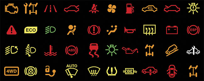
Figure 2. A sampling of the more than 150 standardized telltale symbols specified for use in automobiles worldwide. Courtesy of Radiant Vision Systems.
Automotive display screens are growing in popularity, taking over more surfaces of the vehicle as the industry progresses. Due to recent backup-camera regulations, in fact, at least one display screen (often located in the vehicle center stack) is required for all new passenger car models. High-end brands such as Tesla and BMW are also starting to introduce fully digital instrument clusters. Nevertheless, individually illuminated symbols remain in the vehicle in various forms, and most automakers still rely on a traditional backlit dashboard panel for essential instrument cluster functions and indicators.
Beyond standardizing symbol shapes and colors, regulations also specify minimum visual clarity and brightness tolerances. The U.S. National Transportation Safety Board dictates the location, identification, and illumination of telltales and indicators. Other major U.S. requirements include:
• MIL-DTL-7788 (formerly SAE AS7788) — the Panels, Information, Integrally Illuminated standard for backlit
instrument panels (such as the automotive symbols and flight deck controls in an aircraft).
• FMVSS 111 — the Rear Visibility standard, as it pertains to indicators in vehicle rearview mirrors (such as blind-zone indicators).
Other regions have parallel sets of regulations, such as the Canada Motor Vehicle Safety Standard 101, the European Union’s ECE regulations, and the Chinese Standard GB/T 4094.2-2017.
These standards and similar ones around the world include specifications for the luminance (brightness), chromaticity (color), clarity, and shape of warning lights and indicators. Automotive manufacturers must test vehicle elements against these standards to ensure safety and performance, and they must be able to report measurement data to verify compliance. In addition, manufacturers typically must adhere to internal brand or quality specifications. With all these elements to account for amid the evolution of automotive technology and design, the complexity of inspection regimens has rapidly increased.
Inspection challenges
Evaluating illuminated and backlit components — such as controls, instrument panels, and LED light strips — often requires a unique measurement approach. The quality of an illuminated component is determined as much by its photo-
metric qualities (color and brightness, as shown in Figure 3) as it is by the overall integrity (having the correct shape and position, and being free from defects) of its illuminated regions.
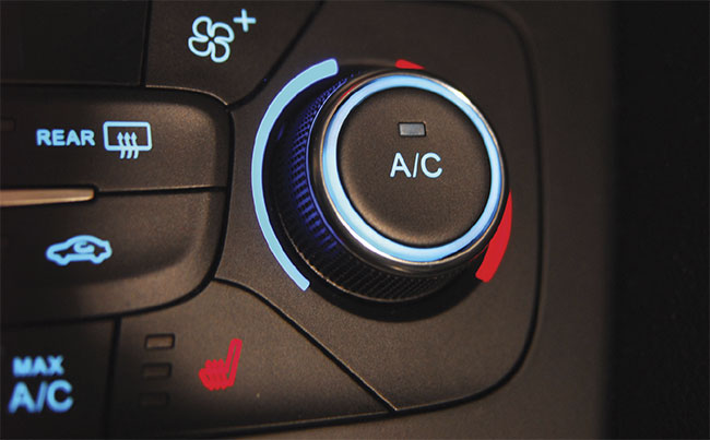
Figure 3. Both the color (chromaticity) and the brightness (luminance) of backlit indicators must be uniform and meet regulatory specifications. Courtesy of Radiant Vision Systems
Accurate measurement requires precise registration of icons and shapes, ensuring that only the illuminated region is used to quantify photometric values and that defects can be detected reliably. Testing the visual performance and quality of all lighted elements in a vehicle requires:
• Absolute measurement of luminance and chromaticity.
• Measurement of the uniformity of luminance and chromaticity across a backlit area.
• Evaluation of the shape and completeness of an illuminated area (identifying defects such as inclusions or exclusions).
• The ability to assess a symbol’s shape and position even if it is rotated or moved.
• Capturing and reporting inspection data to standards and certification entities.
• The ability to perform rapid, automated evaluations in a production environment.
Photometric measurement systems excel at light and color analysis. However, they have traditionally lacked the functionality to provide consistent registration of unique shapes or inspect each shape’s dimensional accuracy. At the same time, standard machine vision equipment has long provided an effective method for registering defined areas within images. But these systems lack the photometric component that enables manufacturers to quantify luminance and chromaticity data.
Traditional inspection systems
Typically, automakers have used a combination of
methods to perform the necessary inspections. However, each method by itself only provides a partial solution:
• Spot meters provide absolute luminance and chromaticity data, but only for a single small area or spot at a time. These meters have no ability to evaluate shape completeness or detect dimensional defects.
• Human inspectors can quickly discern symbol shape, orientation, and completeness, but cannot quantify absolute luminance and chromaticity. Additionally, human inspectors are costly to employ and subject to fatigue and error.
• Machine vision cameras can match characters, shapes, and
symbols to a golden sample to
inspect completeness and detect
defects. However, they cannot measure absolute luminance and chromaticity. These systems also may not be able to perform a test if the symbol location or orientation changes or if the part under inspection is not perfectly aligned — as frequently happens with the laser-cut components on the production line. This issue requires complex fixturing — holding a part in place relative to the inspection system — as part of the setup.
Photometric measurement systems are fundamentally designed to evaluate broad distribution areas produced by light sources or rectangular areas of displays. Because of the defined shapes of the symbols, evaluating them when they are backlit has required
either human inspection or a combina-
tion of software and equipment — usually a photometric system and a machine vision system — with each component accomplishing only part of the quality control objective. A photometric system measures the brightness and color of a symbol while, separately, a machine vision system evaluates shape quality (performing defect detection within the registered area).
Symbol quality and defect detection
Most icons on backlit components are produced by laser etching shapes and text into various substrate layers and then combining the layers with plastic overlays and filters. If the etching process is done inaccurately, icons may exhibit defects such as inclusions or exclusions (Figure 4), which manifest as dark or missing areas, or inaccurate contours of the backlit icon. Other defects may include dead LEDs behind the overlay or filter substrate, or debris particles within substrate layers.
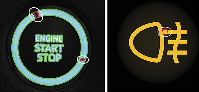
Figure 4. Backlit symbols must be inspected for absolute luminance and chromaticity values and uniformity, and for defects — such as gaps or exclusions (left) or extra elements or inclusions (right) — in the symbols’ shapes and formations. Courtesy of Radiant Vision Systems
Dozens of illuminated components in automobiles are manufactured by various suppliers. This can introduce slight variations between different parts in the same vehicle and different production runs by the same supplier, and between lots of the same part received from different suppliers. With no single inspection system able to perform all the needed testing, manufacturers have had to spend time and money on inefficient or duplicated processes and equipment.
Inspection inefficiencies
Consider just one illuminated element: the blind-zone indicator. These indicators are a critical vehicle safety component, and thus they are subject to strict requirements for shape, position, and luminance and chromaticity values. The symbols are typically manufactured by laser cutting a stencil layer that will overlay an illuminated panel, with the light shining through to illuminate the symbol.
These symbols must be clear, visible, and legible under all ambient conditions. Yet they are particularly challenging to inspect because fixturing and alignment must be extremely precise. Millimeter differences in laser cutting or part placement can interfere with effective measurement by machine vision systems.
In one case study, a major tier one component manufacturer maintained two separate inspection lines to complete all of the inspections needed for backlit components. This resulted in additional equipment, labor costs, and inefficiency because its blind-zone indicator components had to be subjected to inspection in two phases, as follows:
• On the first line, a machine vision system ascertained shape and completeness of the symbol, confirming there were no defects, such as inclusions or exclusions.
• On the second line, a photometric system measured luminance and chromaticity values and assessed uniformity.
In practice, this multiphase process required the manufacturer to move each part from one inspection station to another — to inspect it twice. This was time-consuming and labor-intensive. It also carried a risk of introducing variations from one phase to the next. The manufacturer needed a single, integrated system that combined photometric and computer vision capabilities.
A new approach
Automotive manufacturing inspection has traditionally been a machine vision-dominated realm. Some people may think of imaging photometers and colorimeters primarily in the context of illuminated display inspection of consumer devices such as laptops and smartphones. In fact, the ability of photometric and colorimetric imaging systems to measure luminance and chromaticity values in a spatial context has much broader application, especially when enhanced with computer vision capabilities.
Using this machine vision and photometry approach, the tier one manufacturer was able to consolidate the two inspection lines into one. The manufacturer can now perform comprehensive symbol inspection for shape, orientation, luminance, and chromaticity using a single system, in a single measurement image. At the same time, the manufacturer can capture a complete set of measurement data that can be used for both internal quality control and for reporting to regulatory entities.
Dynamic registration
Traditional machine vision systems are limited in their ability to accurately assess illuminated regions that may be rotated or appear outside of a fixed position. In contrast, photometry-based imaging systems are designed to recognize and characterize unexpected or random defects, such as a character that is out of alignment. This capability is referred to as dynamic registration — meaning that, regardless of slight changes in position or orientation of components or component features, the system can locate and register regions of interest for each symbol area (Figure 5). This simplifies component placement and fixturing on the inspection line.
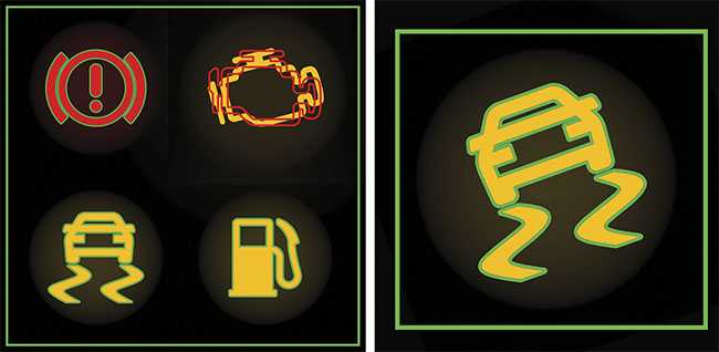
Figure 5. Photometric imaging enables a system to register icons and shapes based on trained registration regions. Global registration (left) ensures that icons are accurate relative to one another. Local registration (right) ensures that icons can be accurately measured and inspected regardless of location or orientation. Courtesy of Radiant Vision Systems.
By leveraging dynamic registration, photometric systems can capture more precise luminance, chromaticity, and other measurements within the region of interest of unique shapes such as automotive telltales and indicators. This precision ensures the accuracy of photometric data while at the same time enabling machine vision capabilities to be applied accurately to locate the region of interest and detect defective areas caused by inaccurate laser etching or errors in overlays, filters, or other substrate layers (Figure 6).
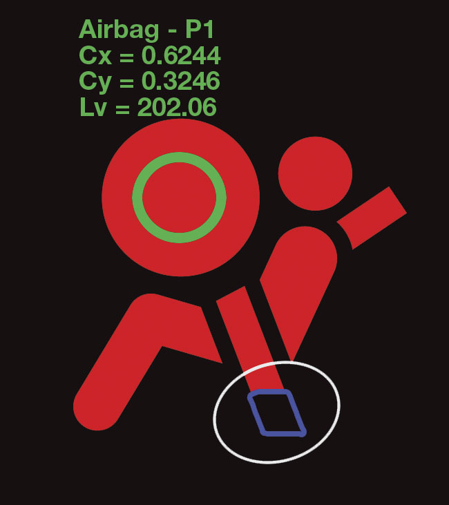
Figure 6. A single measurement includes dynamic symbol registration, unlimited user-defined points of interest within a symbol (luminance, chromaticity, and more) for photometric measurement, and automatic defect detection of inclusions, exclusions, and other deformations of the shape. P1: a defined point of interest (POI); Cx and Cy: chromaticity coordinates; Lv: luminance.
Courtesy of Radiant Vision Systems.
Bringing together the science of
photometry and machine vision capabilities gives automotive manufacturers a complete tool set with which to address inspection needs within a single solution, making it easier to meet vehicle safety requirements.
Meet the authors
Matt Scholz is the automotive business leader at Radiant Vision Systems. He works with many of the world’s leading automotive brands, OEMs, and tiered suppliers to help solve visual inspection challenges in the R&D process and on vehicle manufacturing production lines; email: [email protected].
Anne Corning is a technical writer with Radiant Vision Systems. She has spent more than 15 years researching and writing about technical and engineering topics in the data center, software, LED, automotive, and consumer electronics industries; email: [email protected].