Computer-generated holography is a quick method for measuring aspheres in a production environment. But care is required to minimize errors.
JANET LIM, EDMUND OPTICS SINGAPORE
Aspheric lenses are preferred over conventional spherical lenses in many optical systems for their
high optical performance and lightweight and compact form factor. However,
measuring aspheric surfaces is not a straightforward process. Metrology
options are typically based on interferometry or profilometry1 (Figure 1). To
measure an asphere interferometrically, the reference wavefront must match that of the nominal aspheric form. A computer-generated hologram (CGH) aspheric null achieves this by converting the wavefront from the aspheric surface into a spherical wavefront and superimposing it over the reference wave in the interferometer.
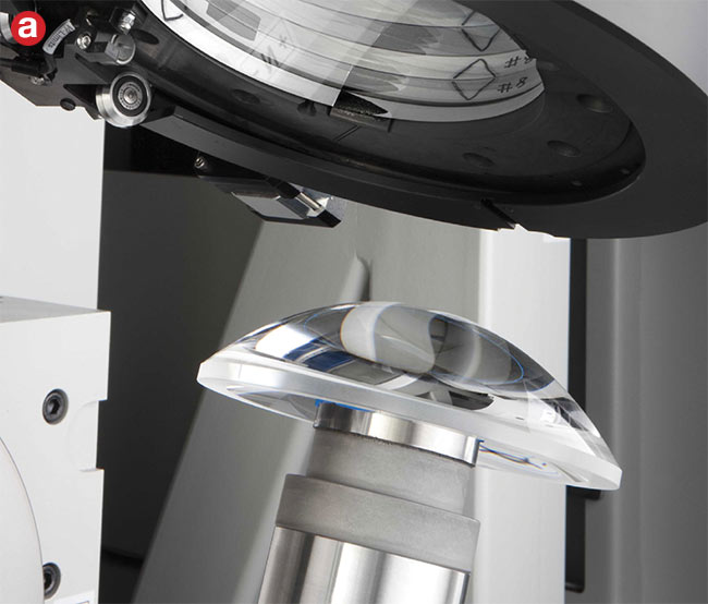
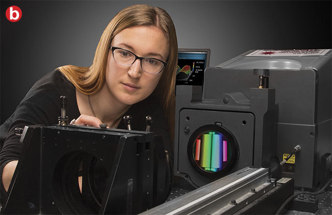
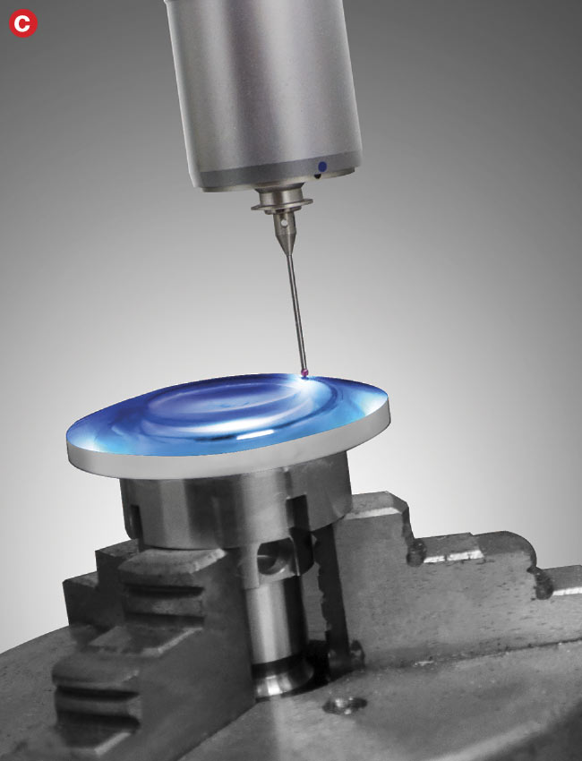
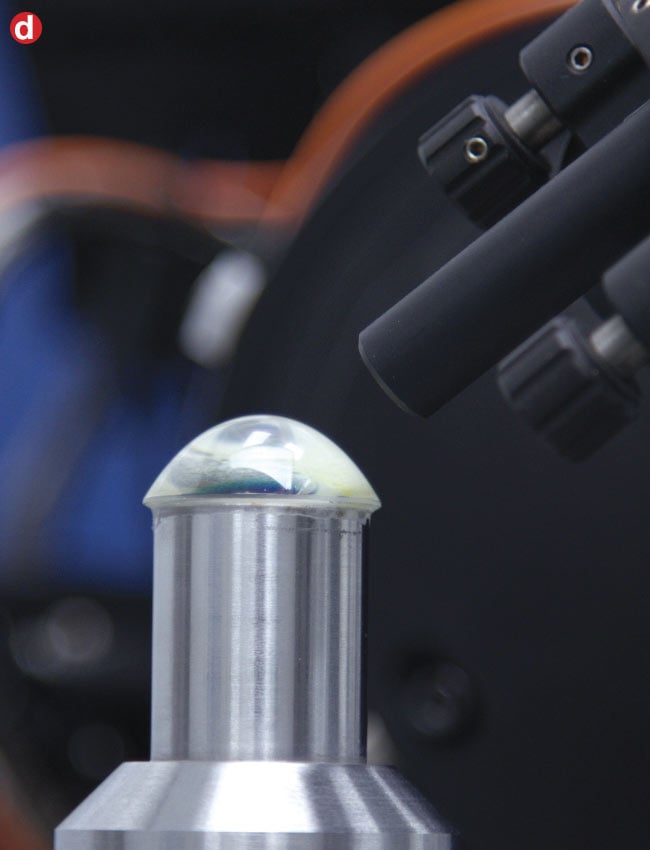
Figure 1. Typical asphere metrology choices include stitching interferometry (a), computer-generated holograms (b), mechanical contact profilometry (c), and optical noncontact profilometry (d). Courtesy of Edmund Optics.
What are CGHs?
CGHs are substrates etched with a
pattern that provides accurate wavefront control. The underlying mechanism is based on the theory of diffraction, in which waves passing through an aperture are bent according to the density of the periodic pattern. A CGH pattern is designed parametrically so that light passing through the hologram perpendicularly hits the surface under test (Figure 2). Each hologram design is unique to an aspheric prescription and complements a predetermined transmission sphere.
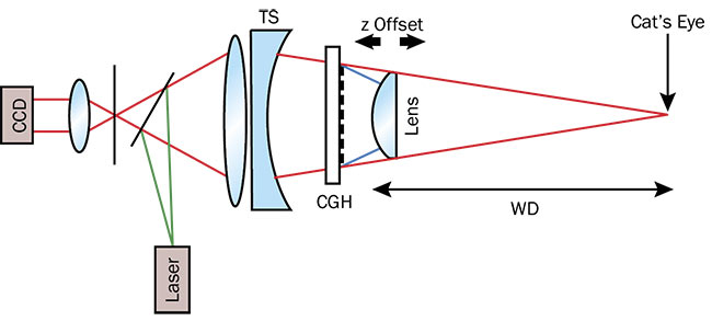
Figure 2. A typical setup for interferometric measurement of aspheres using a computer-generated hologram (CGH). TS: transmission sphere; WD: working distance. Courtesy of Edmund Optics.
The accuracy and validity of the hologram measurement is affected by errors stemming from the design, fabrication, and alignment of the substrate2. Users cannot eliminate errors (if any) that emerge from design or fabrication; however, they can correct for small errors caused by misalignment.
Measurement steps
The measurement process starts with the installation of a CGH at a location specified by the manufacturer or designer, somewhere between the transmission sphere and the sphere’s cat’s-eye focus. The hologram position will need to be slightly adjusted to remove any tilt and power fringes from the alignment interferogram.
Upon completion of hologram alignment, the lens is moved to a position where the rays are perpendicular to the test surface. This position — the working distance — is also provided by the CGH manufacturer or designer. Once positioned at the correct working distance, the test surface will need a slight adjustment to achieve an interferogram with the least spatial aberration. Alignment of the test surface is one of the most challenging steps in hologram measurement. Differentiating alignment error from real residual error on the test surface is often difficult. Lateral misalignment typically leads to tilt, coma, and trefoil, while longitudinal misalignment leads to power and spherical aberration3.
CGH manufacturers often provide the estimated amount of Zernike error that will result from the misalignment of a perfect lens. However, the misalignment window is usually assumed to be small (~10−1 mm) and does not provide information relevant to higher-order Zernike errors.
Lateral misalignment is reduced by keeping the dominant alignment error, or coma, to its minimum. Coma is a non-rotationally symmetric error often caused by an off-centered lens and is unlikely to appear as a significant residual error on the surface. Hence, minimal coma is a good benchmark of lateral alignment.
The dominant longitudinal alignment errors are power and spherical aberration. Defocusing the test surface can diminish the residual power and spherical aberration. However, this implies that the measurement no longer occurs at the working distance.
Longitudinal misalignment
A lens with a large power tolerance allows for significant power error on its test surface. This implies that a measurement at the working distance could lead to high-density power fringes, which the interferometer cannot resolve (Figure 3). Conversely, defocusing removes high-density power fringes (Figure 4) but introduces longitudinal misalignment that results in inaccurate spherical aberration on the test surface.
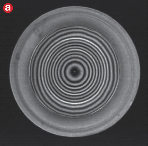
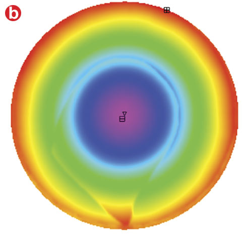
Figure 3. High-density fringes are not resolvable by interferometer and create artifacts in measurement results. An interferogram measured directly from an interferometer (a). The resulting map of the surface generated (b). Courtesy of Edmund Optics.
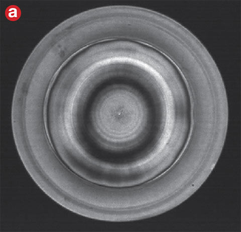
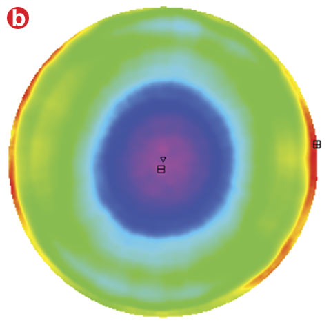
Figure 4. Defocusing removes high-density fringes to create a resolvable image. An interferogram measured directly from an interferometer (a). The resulting map of the surface generated (b). Courtesy of Edmund Optics.
Figure 5 illustrates measurement of an aspheric test surface at the working distance that is misaligned longitudinally. Note that the longitudinal misalignment led to a significant third-order spherical
aberration (SA3), and its magnitude intensifies with increasing longitudinal misalignment. The data empirically shows that the relationship is linear, and this holds true regardless of the aspheric prescription.
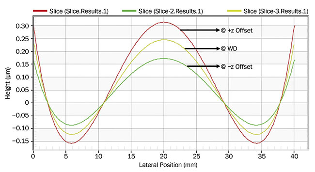
Figure 5. Induced third-order spherical aberration (SA3) at various locations from working distance. Courtesy of Edmund Optics.
The data in Figure 6 derives from the optical design software (ZEMAX) used to model error propagation arising from longitudinal misalignment for various aspheric surfaces. The results are very close to the measured spherical aberration error. Notice that the gradient is different for each unique asphere.
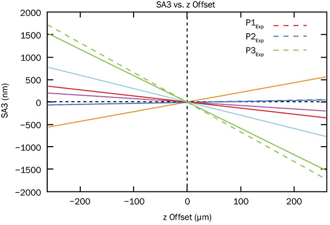
Figure 6. Software model comparing propagated (solid lines) and measured (dashed lines) third-order spherical aberration. Courtesy of Edmund Optics.
This linearity is described using the following equation:
SA3Measured = α z + SA3Actual
where,
z = offset from working distance (µm);
α = coefficient of aspheric departure
(nm/µm).
The coefficient α (gradient) is related to the aspheric departure from its best-fit sphere (Figure 7). Coefficient α is positive when the aspheric departure is above its best-fit sphere, and negative when the aspheric departure is below. The magnitude of coefficient α intensifies with higher aspheric departure from its best-fit sphere (Figure 8).

Figure 7. Illustration of aspheric departure from its best-fit sphere (BFS). AD: aspheric departure. Courtesy of Edmund Optics.
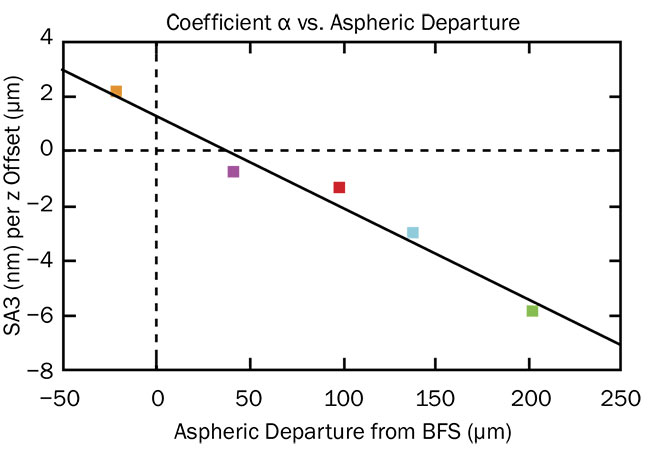
Figure 8. Comparison of coefficient α of each lens in Figure 5. Courtesy of Edmund Optics.
However, there is no definitive way to correlate the coefficient α of an aspheric surface to its aspheric departure from the best-fit sphere. Aspheres are primarily
designed to reduce spherical aberration from a lens system4 (Figure 9). Increasing
aspheric departure would achieve this effect; however, the initial spherical aberration from each lens system is different and therefore requires different degrees of aberration compensation. In other words, an aspheric departure of 100 µm for a small best-fit sphere does not have the same effect on reducing spherical aberration as that of a larger best-fit sphere.

Figure 9. The steps in aspheric lens manufacture. Courtesy of Edmund Optics.
Spherical aberration
In manufacturing, to prevent induced third-order spherical aberration (due to measuring at an offset) or high-density fringes (due to measuring at working distance), manufacturers perform a radius correction to ensure the test surface has low power before measuring it via CGH at the working distance. However, this step is unnecessary if the amount of induced third-order spherical aberration caused by longitudinal misalignment can be determined via design software or by empirically measuring the test surface (Figure 10). Both methods establish the linear relationship between third-order spherical aberration and longitudinal misalignment for the respective aspheric surface. Figure 11 illustrates measurement of a lens at an offset of 0.4 mm from working distance. The measurement compensates for the amount of induced third-order spherical aberration caused by the offset. The result from the compensated map is comparable to the actual measurement taken at working distance.
Design Software
(e.g., ZEMAX, OSLO)
1. Import aspheric prescription.
2. Design null lens.
3. Calculate error propagation at
<N> z Offset.
4. Extract <N> spherical aberration.
5. Establish linear relationship.
|
Empirical Measurement
1. Manufacture first low-power part.
2. Measure at <N> z Offset.
3. Extract <N> spherical aberration.
4. Establish linear relationship.
|
Figure 10. The amount of spherical aberration caused by longitudinal misalignment can be determined using one of two methods: design software or empirical measurement. Courtesy of Edmund Optics.
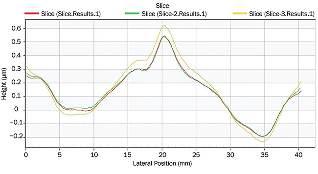
Figure 11. A measurement comparison of an error-compensated lens surface, showing deviation from the ideal aspheric surface (height). Compensated measurement at 0.4 mm offset (α) plus factoring in the actual SA3 (red). Measurement at WD (green). Measurement at 0.4 mm offset without factoring in the actual SA3 (yellow). Courtesy of Edmund Optics.
CGH interferometry is a fast and accurate metrology technique for high-volume aspheric lens production. Errors can emerge from design, fabrication, and alignment, though lens manufacturers can minimize the impact of errors by ensuring accurate alignment during the measurement process — preferably without introducing additional steps that might compromise efficiency.
Longitudinal misalignment can induce significant third-order spherical aberration, which manifests in a linear relationship that can be correlated via design software or by empirically measuring the test surface. By compensating for error on a longitudinally misaligned aspheric surface, it is possible to achieve an ideal alignment.
Meet the author
Janet Lim received a Master of Science in physics from the National University of Singapore. She works on optical metrology as an R&D engineer at Edmund Optics Singapore; email: [email protected].
References
1. A. Frantz (September 2016). Measuring aspheres: selecting the best technique.
Photonics Spectra, www.photonics.com/a60947.
2. P. Zhou and J.H. Burge (2007). Fabrication error analysis and experimental demonstration for computer-generated holograms. Appl Opt, Vol. 46, Issue 5.
3. F. Lucas et al. (2019). Alignment errors vs. measurability for null-measurements of aspheres. Proc Optical Design and Fabrication 2019 (Freeform, OFT), OSA Technical Digest (Optical Society of America, 2019), paper OW4A.3.
4. J. Kumler (2005). Designing and specifying aspheres for manufacturability. Proc SPIE, Vol. 10315, Optifab 2005: Technical Digest.