Like any material, optical coatings can perform differently in different environments. Ignoring the influence of temperature can turn optical coating specifications into a moving target.
JOEL BAGWELL, BRANDYWINE PHOTONICS
What happens when optical coatings get very cold? There should be little difference in a thin film’s optical performance at room temperature test conditions versus its use conditions.
But this is not always the case. Performance varies at different temperatures, and systems engineers, program managers, and other stakeholders must account for when and where these coating performance differences occur to realize ideal instrument performance.
In shortwave infrared (SWIR), midwave infrared (MWIR), and longwave infrared (LWIR) imaging systems, critical components are sometimes cooled to
improve signal-to-noise ratios, and specifically to mitigate factors that contribute to degradation in the noise-equivalent temperature difference. This difference is a measure of a thermal imaging system’s ability to discern between two very close temperatures.
When measuring temperature differences, it is desirable to cool the focal plane array to very cold temperatures, such as that of liquid nitrogen at 77 K, or the even lower temperatures achieved through cryogenic cooling. Additionally, when these systems are deployed in vacuum environments such as in a low-Earth-orbit remote sensing telescope, the optical trains may be cooled to reduce background thermal noise sources even further.
The impact of thermal cooling effects on optical coatings must be considered to
ensure predictable and reliable performance in the final system engineering solution.
Three telescopes
Consider the three instrument configurations shown in Figure 1. All three are current multispectral telescope design configurations for low Earth orbit that are being funded by Small Business Innova-
tion Research (SBIR) grants through NASA and the U.S. Air Force.
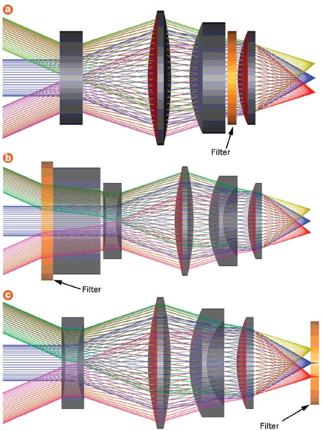
Figure 1. Three real-world multispectral telescope design configurations intended for low Earth orbit. To ensure predictable and reliable performance in the final system engineering solution, the impact of thermal effects on optical coatings must be considered. Four lens elements, with the filter in the middle, are cooled to 220 K to reduce thermal background noise (a). A similar design with the bandpass filter affixed to a gas cell on the front of the instrument. Both the gas cell and filter are cooled to 150 K using a cryocooler (b).
The optical bandpass filter is affixed to a cooled focal plane and is held at 77 K alongside the detector (c). Courtesy of Brandywine Photonics.
Figure 1a shows a multispectral telescope design targeting the MWIR band. It comprises four lens elements, an optical bandpass filter that resides in semicollimated space in the telescope, and a cooled detector. In this case, the telescope optics are cooled to 220 K to reduce thermal background noise.
Figure 1b shows a similar multispectral telescope design in which the bandpass filter is affixed to a gas cell on the front of the instrument. The gas cell and filter are cooled to 150 K using a cryocooler. Such a low temperature is necessary to maintain stability of the cell constituent gas. Additionally, the filter’s location is necessary to ensure that the instrument’s gas correlation physics will work properly.
Finally, Figure 1c shows a third configuration with another similar MWIR telescope. The optical bandpass filter is now affixed to the cooled focal plane and is held at 77 K alongside the detector. This configuration is optimal for blocking all out-of-band thermal noise from any upstream sources.
Two varieties of optical coatings are present in all of the imaging systems shown in Figure 1. First, nearly every optical surface is coated with an antireflective (AR) thin film that is deposited
in approximately three to nine distinct layers of alternating high- and low-index materials. These AR coatings are commonly deposited using electron-beam evaporation with ion-assisted bombardment to aid in environmental stability.
Second, the optical bandpass filter consists of hundreds of thin-film layers alternating between high- and low-index materials. These filters are most often fabricated using either ion-beam sputtering or a form of magnetron sputtering due to the high layer count and required deposition accuracy.
Figure 2 shows representative curves for the MWIR multispectral telescope’s AR coating and its optical bandpass
filter.
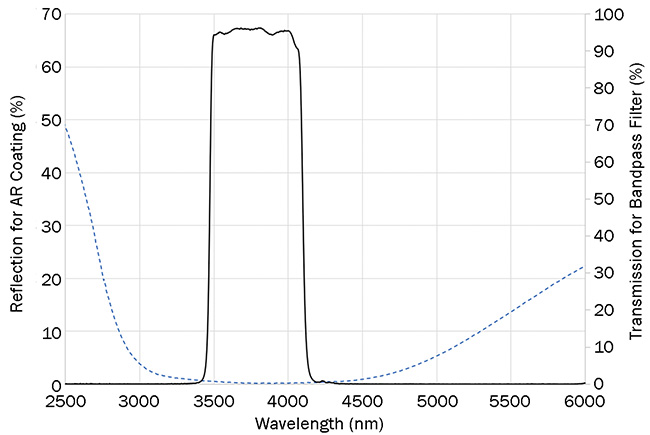
Figure 2. A MWIR antireflection (AR) coating and bandpass filter at room temperature. Courtesy of Edmund Optics.
To achieve the desired performance for either an AR coating or an optical filter,
it is crucial to have a certain degree of control over two critical design parameters — the film’s physical thickness and the index of refraction of each thin-film layer — both during and after deposition.
Variations in either the physical thickness of a layer or its index of refraction
affect its optical thickness (in other words, the thickness divided by the index), and can cause performance to drift.
The difference in the index of refraction between a high-index material and low-index material is known as index contrast. A high contrast between two thin-film materials can do more spectral work — such as producing steeper slopes on bandpass transitions or achieving higher out-of-band blocking. Conversely, pairing two low-contrast materials creates films that perform well across wide spectral bands to provide wider bandpasses or spectral blocking across a wider wavelength range. If the index contrast changes between the high- and low-index materials, further performance drift can be expected because index contrast is a critical design parameter.
Anticipating drift
What is of interest here is whether lower temperatures affect the optical thickness and/or contrast of the thin-film material pair. If so, then a shift in coating performance is likely to occur and the systems engineer will need to determine whether the drift is acceptable, and if not, it must be accounted for in design. The underlying point is that thin-film materials have two key characteristics that can contribute to a shift in each of the design parameters described for thin films.
First, a thin-film material will undergo a change in index of refraction with a corresponding change in temperature. This is known as dn/dT. As a result, when temperature changes, the thin film’s Fresnel reflectance will change. Fresnel reflectance will also be altered when high- and low-index materials’ dn/dTs are different, because their respective indices change at different rates due to changes in temperature, thereby altering index contrast.
Second, all thin-film materials have a characteristic coefficient of thermal expansion (CTE). CTE is the degree of change in a material’s physical dimension resulting from of a change in temperature.
Both dn/dT and CTE are contributing factors to a thin film’s performance shift over a specific temperature range, because interference-based designs rely heavily
on the reflectance and phase of light at
the boundaries of thin films (Figure 3).
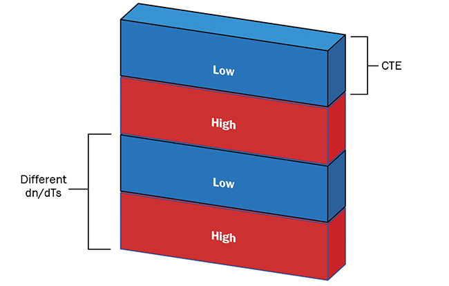
Figure 3. A schematic of a thin film in which the coefficient of thermal expansion (CTE) changes the physical film thickness, while dn/dT (the temperature coefficient of the refractive index) changes the relative difference in index (contrast) between layers. Courtesy of Brandywine Photonics.
The effect can be analyzed using a simplified model of a MWIR bandpass filter comprising low-index zinc selenide (ZnSe) and high-index silicon (Si) layers. When no special design considerations are implemented for athermalization of thin films or for extreme out-of-band blocking, the films represented in Figure 4 serve as a simple illustration of the boundary case for a bandpass filter.
Figure 4 exhibits temperature-related shifting as it applies to a simplified MWIR filter example. In the filter’s nonoptimized condition, the shifts are linear. Figure 5 shows the percentage shifts for the center wavelength and bandpass.
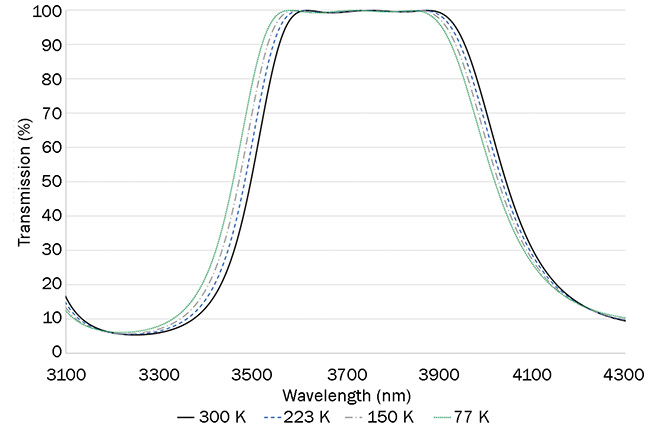
Figure 4. A simplified model of a MWIR bandpass filter. Courtesy of Edmund Optics.
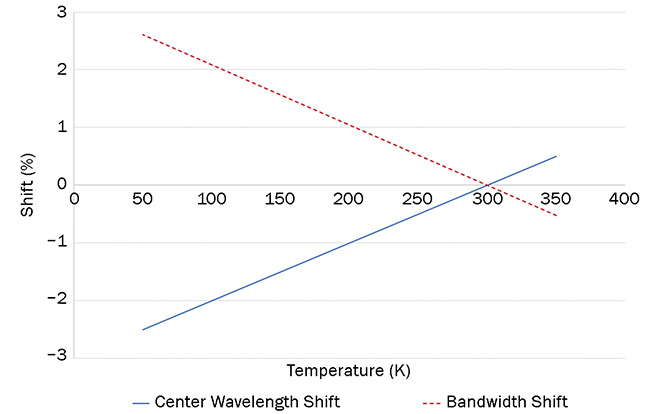
Figure 5. Percentage shifts due to change in temperature versus center wavelength and bandwidth for the simplified filter. Courtesy of Edmund Optics.
For antireflective coatings, spectral shifts on the order of 3% are often negligible against a performance metric of broadband low reflectivity. However,
for optical bandpass filters, such shifts
on the rising or falling edges can have catastrophic effects. For instance, the MWIR band in Figure 2 was selected because it corresponds to an atmospheric transmission window. Shifts on the order of 3% would greatly affect radiometric assumptions for observing weather phenomena.
In practice, filters such as the one shown in Figure 2 will exhibit more complicated performance shifts when those changes result from shifts in dn/dT and CTE. Factors such as the number of reflecting cavities in the filter, the high or low index of the spacing layers, or the physical structure of the thin film will all cause nonlinearities in the types of shifts shown in Figure 5.
In the filter represented in Figure 2, bandwidths and center wavelengths were actually shown to reverse course as temperatures changed from 300 to 77 K, with the nominal condition reached at 223 K, where the design is intended to operate.
Figure 6 further shows that the rising
edge of the bandpass filter actually changes position from high- to low-
temperature situations, while the falling
edge follows the more expected shortwave shift predicted in Figure 5. However, the magnitude of the shifts in Figure 6 has been reduced to the order of 0.5%, which is acceptable for the system’s intended remote-sensing application.
Conclusion
The key takeaway is that thermal shifts will occur in thin-film design. Left unchecked, shifts on the order of 3% can be expected over the course of a 230-K temperature shift for a ZnSe/Si material
system. Thin-film material systems can be athermalized when CTEs and dn/dTs
are plotted in such a way to minimize changes in reflectance at specific temperature ranges. Those who specify filters for use in very cold systems must either tolerate the sort of percentage shifts illustrated in Figure 5 or place additional requirements on their thin-film design and on filter suppliers to minimize the thermal-shift effect.
There are many material systems for filters and AR coatings beyond those described here, and each demonstrates a characteristic relationship between dn/dT and CTE that can affect performance over a wide temperature range. Further, the thin-film design form used will introduce nonlinearities at different temperatures, as illustrated in Figure 6. As a consequence, it is wise to add design-and-test requirements for thin-film performance
at the specified use temperature when
designing or purchasing interference filters. Finally, if the ability to test at the
use temperature is not available, then designers must account for temperature-based performance drift in the tolerance budget for their system.
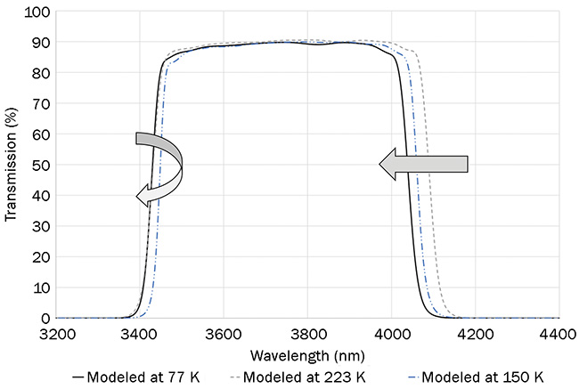
Figure 6. Modeled data of an actual optical bandpass filter used in MWIR flight hardware. Courtesy of Edmund Optics.
Meet the author
Joel Bagwell is the director of R&D at Brandywine Photonics, which develops small weather satellites and instruments. He has 20 years of experience in optical manufacturing, metrology, and product development.
Acknowledgment
The author wishes to acknowledge and thank Chris Cook of Edmund Optics for providing theoretical modeling assistance for Figures 4 and 5.