Large, high-performance mirrors are a critical aspect of numerous optical systems and must meet strict requirements.
NISSIM ASIDA, ELIYAHU BENDER, AND DAVID ALEXANDER, OPHIR OPTICS SOLUTIONS LTD.
When it comes to long-range, multispectral optical systems, large mirrors play an integral role; there are tens of thousands of optical units containing large mirrors around the globe. With minimum diameters starting at 200 mm, the largest mirrors range from 8.2 m in diameter (single mirrors) to over 10 m (segmented). They take many shapes — spherical, aspheric, parabolic, or freeform — and are used for a wide spectrum of light, including visible, UV, and IR.
Over the last 10 years, optical systems with reflective elements have been used by system integrators in the defense and aerospace industries, in surveillance and monitoring, and in certain commercial applications. For example, large mirrors may be integrated into the optical systems of large unmanned aerial vehicles (UAVs) in long-distance aerial monitoring of agricultural field temperature using IR. The most recognized applications of large mirrors have been in the aerospace industry, for satellites and long-range telescopes.
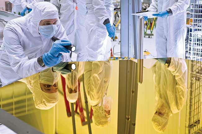
An engineer examines the Webb telescope primary mirror in the cleanroom at NASA’s Goddard Space Flight Center, Greenbelt, Md. Courtesy of NASA/GSFC/Chris Gunn .
Reflective systems generally have long focal length and are meant for long-distance surveillance, possibly tens of kilometers. Reflective telescopes may use one or more on-axis or off-axis mirrors to produce high-resolution images. Many telescopes, as well as other optical systems utilizing large mirrors, are catadioptric systems that rely on a combination of lenses and curved mirrors, which maximizes error correction and allows for a wider field of view.
Strict specifications
The production of large mirrors presents a unique set of challenges for optical manufacturers. Whether spherical, aspheric, parabolic, or freeform, the accuracy of surface form is of utmost concern. Tolerance requirements of the order of 0.2 fringe of helium-neon (HeNe) light are not uncommon. The off-axis form is specified in systems that cannot tolerate the central obscuration. Off-axis mirrors are substantially more challenging in terms of mirror fabrication, testing, and system assembly.
Large mirrors are often used for multi-spectral applications, which means they must perform to a high level across a wide range of wavelengths. They also must have minimum roughness, especially when they are used in VIS wavelength, under 40Å rms (root mean square), to prevent light from scattering. Additionally, as detectors are increasing in resolution, there has been growth in the demand for mirrors with increasingly accurate surfaces.
In order to meet the strict specifications required, manufacturers must employ cutting-edge technologies, such as advanced CNC (computer numerical control) grinding and polishing, and diamond turning, for spherical, aspheric, parabolic, and freeform mirrors up to 700 mm in diameter, whether on-axis or off-axis. These types of large mirrors have a radius tolerance of 0.05 percent, irregularities less than 0.5Fr P-V, 0.1Fr rms at 0.633 μm, and a roughness of less than 40 Å rms, resulting in high accuracy and low scatter. Reflective coatings assist with spectral performance and surface durability.
Reflective optical design
The design process is constantly evolving to meet new requirements. An all-reflective design, similar to the classic Cassegrain telescope, with an f-number of f/3.4, illustrates the effect of surface figure on performance (Figure 1). Reflective systems of this type are most advantageous in cases where there is a large ratio of effective focal length (EFL) to physical length. Here, the EFL is 1000 mm, whereas the overall length of the optics alone is 200 mm. A ratio of 5 to 1 is uncommon in the case of refractive systems. The modulation transfer function (MTF) of this system, at 100 lines per mm (lpmm), is 0.7 for the wavelength 500 nm. This corresponds to the diffraction limit.
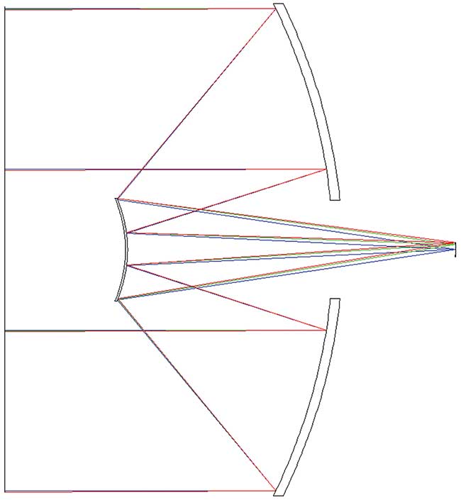
Figure 1. A light path in a Cassegrain telescope. Courtesy of Ophir Optronics Solutions Ltd.
In this simple, all-reflective case, with the 5:1 ratio of EFL to length, the field curvature is substantial, and there is significant astigmatism at field positions off-axis. This astigmatism manifests itself by the sharp drop in the MTF plot in Figure 2, where the performance of the 0.25° field is much degraded. (As the performance is good only in the center and much degraded in the fields, this example is for illustration only and should not be considered a practical design.)
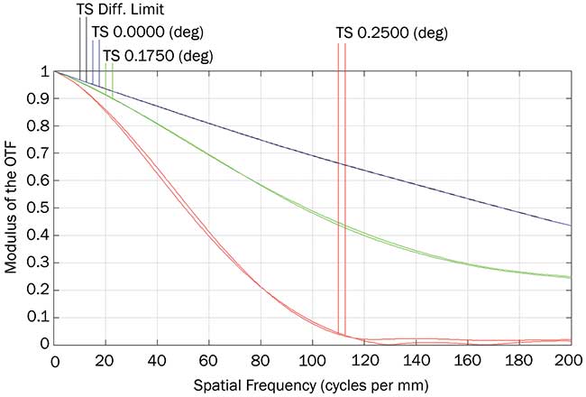
Figure 2. A modulation transfer function (MTF) plot shows astigmatism at field positions off-axis. OTF: optical transfer function. Courtesy of Ophir Optronics Solutions Ltd.
In general, refractive elements are needed to flatten the field. The classic solution is the Schmidt corrector plate, which is placed in front of the primary mirror, in roughly the same axial position as the secondary mirror. Alternatively, refractive elements between the secondary mirror and the image can simultaneously correct the field and change the EFL. The disadvantage of refractive elements in the system is that they limit the wavelength spectrum and introduce chromatic aberration.
The surface figure of reflective elements is extremely important for high-resolution systems. The amount of wavefront error caused by a given surface irregularity in reflection is more than double that caused by the same surface in refraction. To model the relationship between surface irregularity and imaging resolution performance, Zernike standard term 11 is applied on the primary mirror:
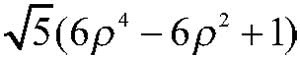
Then, the MTF of the center field is plotted against rms surface error for five representative cases (Figure 3).
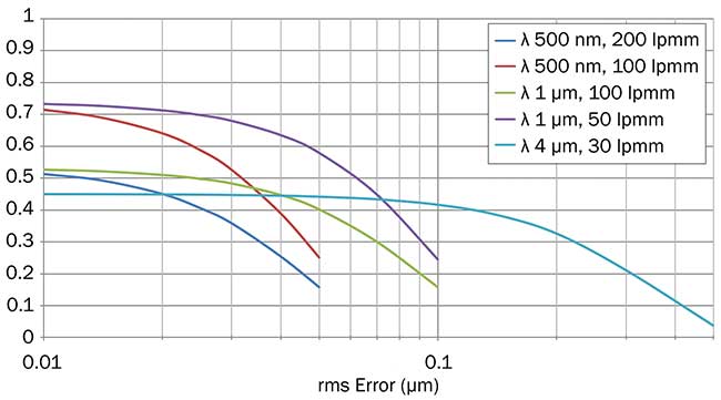
Figure 3. An MTF of center field versus rms error for five representative cases. Courtesy of Ophir Optronics Solutions Ltd.
Rms errors as little as 0.02 µm can be significant in high-resolution visible light systems; this is equivalent to 0.03λ rms
at λ = 633-nm test wavelength. For IR systems in the region of 4-µm wavelength, the diffraction limit of resolution is much lower, and so, rms errors as high as 0.1 µm can be tolerated.
Manufacturing challenges
Whether aluminum (Al), silicon (Si), germanium (Ge), or copper (Cu), the mirror’s raw material is of crucial importance. Often, aluminum is recommended because it is very robust. In particular, RSA 6061, a proprietary super aluminum alloy, is ideal for multispectral applications. This material allows low levels of surface roughness, unattainable by conventional Al 6061. While higher roughness usually has no consequence in IR systems, a low surface roughness is vital for visible and shortwave-infrared (SWIR) applications. RSA 6061 has the added advantage of being somewhat stronger than conventional Al 6061.
Once material has been selected, a typical process includes these stages: (1) preparing the mirror blank, (2) roughing, (3) preliminary measurement, (4) final surfacing of the mirror, (5) final measurement, (6) coating, and (7) final testing. Manufacturing through these stages presents its own challenges.
After preparing the blank, the material undergoes heat treatment. The mirror’s back surface must permit stress-free mounting, and upon assembly, the mirror must not permit stress to bleed through to the optical surface. Threaded holes, if they are too near the mirror surface, will almost certainly lead to surface distortion. There must also be ample surface area to hold the mirror onto the cutting machines.
The production environment is a core concern. For example, aluminum has a relatively high coefficient of thermal expansion (αL = ~26 ppm/°C) compared to other diamond-turned materials, such as germanium. Therefore, production areas must be temperature controlled.
Additionally, some machines are seismically isolated.
When designing aluminum mirrors, designers must take advantage of the fact that the diamond-turning machine is actually a sophisticated CNC lathe. Therefore, critical mechanical dimensions can be attained to demanding tolerances. For instance, the distance “d,” which may be the distance between the center of the concave mirror and a flat mounting surface, can be within a few microns, as both surfaces can be generated with the same tool. Surfaces like these allow precision and no-nonsense assembly because of their high degree of flatness and roughness.
Cleaning is another key aspect. In general, cleaning aluminum is not a trivial procedure, and preparing mirrors for testing and coating is an essential skill. In order to prevent cosmetic blemishes, mirrors must be thoroughly and carefully cleansed immediately after diamond turning has finished.
Surface measurement
Perhaps the most critical aspect of the production process is the ability to measure the optical surface accurately and reliably. Optical shops have many options for measuring such surfaces. Historically, parabolas have been the preferred shape of large mirrors, and this special conic contour is readily measured using the autocollimation method. In theory, parabolas by themselves also promise low spherical aberration.
A typical autocollimation system consists of a commercial interferometer, a transmission sphere, and a large flat mirror with a central hole. Inherent aberrations from each of these systems’ components, however, add to the overall error. Often, built-in errors can be
compensated for by performing rather complicated calibration and nulling. Precise Fizeau transmission spheres can be used to reduce these built-in errors. A disadvantage of the autocollimation system is that measuring the radius of curvature is awkward and rough. This is especially magnified for mirrors with no centers.
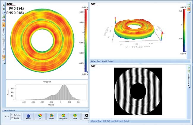
Figure 4. Measurement results for a 190-mm aluminum mirror. Courtesy of Ophir Optronics Solutions Ltd.
In recent years, designs have shifted away from pure parabolas, and the use of various aspheres has increased. Optical shops must therefore be equipped with versatile tools for measuring a wide assortment of aspherical mirrors. A Zygo VeriFire Asphere (VFA) enables precise measurement of the majority of large aspheric mirrors. When measuring mirrors that have no center, the Zygo VFA requires an artificial center plug, which adds some more uncertainty to the equation. Nevertheless, the radius of curvature can be acquired with a high degree of accuracy and low uncertainty.
For very demanding requirements, a CGH (computer-generated hologram) or a DFNL (diffractive Fizeau null lens) can be utilized. Both of these allow for extremely accurate measurement of aspheric mirrors. These tools often add extra features, allowing the measurement of the radius of curvature and surface irregularity in tandem. A distinct advantage of the DFNL over other aspheric methods of measurement, for surfaces with F/no.>1, is that the DFNL itself is the only component needed to check the asphere. For these surfaces, the DFNL is able to bend and collimate the light and create a null.
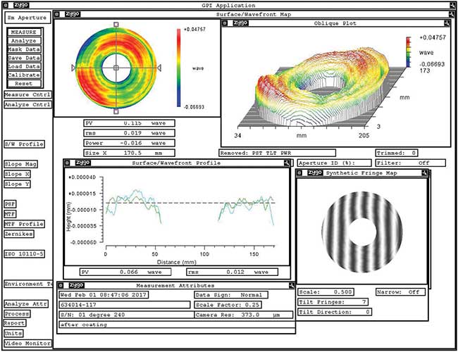
Figure 5. Interferogram of a primary mirror with a central obscuration. Measured surface error: 0.115λ P-V, 0.019λ rms at λ = 0.633 nm. Courtesy of Ophir Optronics Solutions Ltd.
Operators are then able to use interferometric output data to create feedback correction programs. These operations depend on highly accurate processes, with very high certainty. This “measurement correction” feature is only as successful as the accuracy and certainty of the measurement itself. In general, such a measurement correction feature can only deal with circularly symmetrical errors. Because of this, asymmetrical problems, such as mounting stress or thermal issues, cannot be fixed.
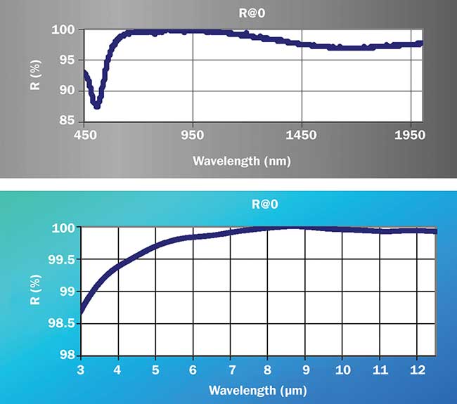
Figure 6. Spectral performance of wide-band protective silver coating on aluminum substrate. Courtesy of Ophir Optronics Solutions Ltd.
Figures 4 and 5 show the results of a 190-mm aluminum mirror with a central obscuration. The results show spherical aberration of less than 0.02λ rms, achieved using advanced tools and equipment. Often, the coating process can degrade the results. In these cases, such effects must be considered in the calculations. Figure 6 shows the spectral performance of wide-band protective silver coating on this type of aluminum mirror.
From design through manufacturing, it is critical to maintain quality throughout the production process, ensuring mirrors will sufficiently meet current performance specifications.
Meet the authors
Nissim Asida, Ph.D., has over 25 years of experience in laser optics. He has served as engineering director of Ophir Optics R&D for the past 11 years. Prior to that, he worked at Elbit’s electro-optics division as project manager. His doctorate is from Bar-Ilan University in nonlinear optics and lasers.
Eliyahu Bender has designed IR optics for Ophir Optics for the past 19 years. Prior to that, he was a lead engineer at Boeing in St. Louis. He has an M.S. in physics from Oklahoma State University.
David Alexander is a senior optical engineer at Ophir Optics and is the in-house specialist in optical metrology and diamond-turning manufacturing of IR components. He has a B.S. from Machon Lev Jerusalem in physics/electro-optics.