Brian Elias, Cal Sensors Inc.
Often a scientist or engineer is tasked with developing a spectroscopic system for which he must choose a source. He may know exactly which architecture, dispersive element, slit size and sensor the application requires, but he may be left to the mercy of marketing propaganda when it comes to the selection of the infrared source. Should he depend on the old reliable technology or venture into a new and innovative source – and what are the benefits? Maybe a lightbulb would work.
The easy way is reviewing the technologies of each emitter type and selecting a specific spectroscopic application.
The use of infrared is expanding as applications that address cost, quality or security issues are developed. Some applications rely on the generation of IR energy from the object itself, but these are rare. Most spectroscopic measurements rely on reflection from, or transmission through, a sample, with the resultant absorbance spectra measurement being made on the transmitted energy. These require sources of IR energy that have characteristics based on the application, on the spectrometer design or on the detector used.
Two choices
Infrared sources or emitters can be broken down into two general technologies: quantum and thermal emitters.
Thermal emitters generate photons by heating material. They are, by nature, broadband emitters whose output characteristic is determined primarily by the temperature of the element as described by Planck’s law. Characterized by high output power, they have long been the standard source for IR spectroscopy. Thermal emitters can be pulsed but require careful design to overcome the intrinsic thermal mass of the heated filament.
Quantum emitters – laser diodes, IR LEDs, etc. – offer good efficiency and can output well into the IR region. They are useful in spectroscopic applications where a monochromatic source is sufficient or preferred. They offer long lifetimes and high pulse rates in modulated applications.
To determine adequacy for a particular application, each of these technologies can be evaluated by the following parameters: size, efficiency, output power, drive requirements, stability over time, cost, lifetime and pulse rate (for modulated applications).
In addition, some detector technologies dictate the type of source used in a system based on their characteristics; for example, because pyroelectric detectors have slow response to incident radiation, a fast-pulsing source would not be appropriate.
Thermal emitters, also called incandescent emitters, heat material to a point where photons are emitted. Modern thermal emitters have their basis in blackbody radiation and typically are characterized by their emissivity (ε), which is defined as the ratio of the radiant emittance of a source to the radiant emittance of a perfect blackbody at the same temperature. Although metals commonly are used as source elements for thermal emitters, they typically have very low emissivity values in the range of 5 percent. A relatively simple process of oxidization can increase their emissivity to more than 80 percent, at which point they have sufficient emissivity to be used as thermal radiators.
Thermal emitters have the advantage of broadband emission and the disadvantages of slow speed – for pulsed applications – and of high drive-power requirements. Some applications rely on a simple tungsten bulb for a source, but the glass or quartz bulb material used often does not transmit the longer wavelengths; for example, quartz transmits only 50 percent of its peak value at 4.3 μm. Recent advances in several areas have brought improvements in dedicated thermal emitters that enhance their use in a variety of broadband applications. MEMS technologies now can produce both spectral and blackbody emitters with very small size and fast pulsing – thanks to the low mass of the emitter – with a resultant limitation of low output power. Deposited film emitters offer a compromise between fast pulsing rates and high power output. In addition, advances in filament emitters have resulted in high pulsing speeds with high output power and long lifetimes.
Several filament configurations for thermal emitters, each with their advantages and disadvantages, direct the designer of spectroscopic systems to choose one over the other.
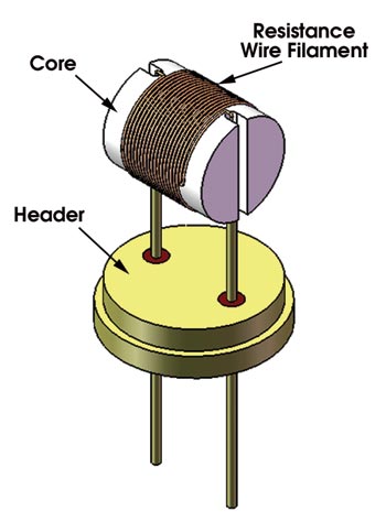 Wound Filament: These emitters provide high power output with relatively low cost and high reliability. They can have a solid or air core, with the former material typically ceramic. In its basic form, the air core wound filament emitter is similar to a lightbulb. The dedicated IR emitter’s advantage is that it can generate IR photons, so all of the materials are designed with that in mind. A ceramic core often is added to produce a more uniform output because the filament heats the core, thus radiating photons. In some multielement detector systems, air core wound emitters can be problematic because the filament coils are imaged on the detector and produce a nonhomogeneous flux field.
The filament material is a resistance wire, often NiCr, or a variety of wires produced by Kanthal AB that are FeCrAl alloys and that offer high-temperature operation (1350 °C for Kanthal A) and long life. Because of the large mass of the source, wound filament emitters do not lend themselves to modulated applications. Any modulation would require mechanical means, such as an optical chopper.
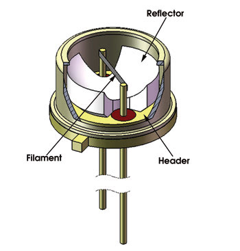 Ribbon Filament: The pulsing speed of an incandescent filament depends on the rate at which the filament can be heated and at which the heat can be removed. Addressing this problem involves the analysis of all aspects of the energy cycle, including filament mass, photon direction, filament “heat sinking” and power-drive design. Ribbon filament emitters are mechanically simple devices, making them cost-effective and reliable. Although tungsten often is used as the filament material, it has very low emissivity, particularly in the infrared, so surface treatments must be applied to enhance the emissivity, and the atmosphere must be carefully controlled to eliminate further emissivity changes resulting from atmospheric interaction. Hermetic sealing with a thermally conductive backfill gas ensures filament emissivity stability as well as a maximum cooling rate during the cooling cycle of the pulsed operation.
Reflectors often are used – as with the wound filament emitters – to direct all possible radiation out of the package, particularly in vertically oriented filaments.
During the “On” part of the pulsed cycle, it is important to impart as much power to the filament as possible without overstressing it from film evaporation at localized heating points. Careful design of the drive wave form and backfill environment can enhance the pulse rate and modulation depth significantly. Careful control of these parameters has produced emitters with pulse rates of nearly 200 Hz at a modulation depth of 50 percent. The emitters also can be operated as steady-state sources and do not have the coil imaging problems associated with wound filament sources.
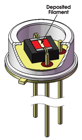 Deposited Filament: Further reduction in filament mass for a high pulsing rate can be achieved through deposition methods. By their nature, deposited film emitters require a substrate to be the mechanical support mechanism, unlike the ribbon filament, which is self-supporting. The deposited filament emitter consists of a film of electrically resistive material deposited onto a substrate of thermally resistive material. The deposited film can be any material that is compatible with film deposition techniques and that has sufficient resistance and emissivity. It also must withstand the high temperatures associated with incandescent photon emission.

Metals such as tungsten have been used, as have various configurations of silicon, where the resistivity is controlled by doping. Doped polysilicon filaments present some problems with dopant migration and often cannot operate at temperatures sufficient for near-IR spectroscopy. A nonmetallic filament’s advantages are that the materials can have higher resistivity and that the drive current requirement is correspondingly lower.
The advantages of the deposited filament source are fast pulse rate and a relatively low cost, depending on the material used. High-volume substrate processing can produce high volumes at relatively low cost. The disadvantage is that the small filament size results in low output power, and for pulsing applications, the thermal mass of the substrate reduces the pulsing speed.
Incandescent emitter failure
A major failure mechanism in incandescent filament emitters is evaporation of the filament, which has two effects that decrease emitter lifetime. As the filament evaporates, it becomes thin, often nonuniformly, because of localized heating resulting from the increased spot resistance. In addition, the evaporated filament deposits onto the window material, decreasing the optical output and increasing the internal temperature of the emitter. Operating these emitters at lower temperatures greatly increases their lifetime. For pulsing emitters, the trade-off always is between low-mass filaments for rapid modulation and sufficient lifetime.
 Microelectromechanical systems
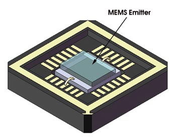
Microelectromechanical systems (MEMS) techniques are being used in a wide array of applications, including IR emitters, to enhance performance using micromachining methods previously not possible. MEMS devices targeted at specific wavelengths or wavelength ranges are available in both thermal (blackbody) and spectral emitter configurations.
A typical thermal MEMS emitter is like the deposited filament emitter, with the added benefit that the substrate on which the filament is deposited can be made into a very thin member. This greatly reduces the thermal mass of the system and enhances the modulated performance.
Many filament materials have been used, including traditional metals and polysilicon. MEMS techniques have produced single-crystal silicon filament sources that can operate at 1200 K with 10.7 mW of total radiated power from a 1-mm2 emitter. Other filament materials used are diamondlike carbon or diamondlike nanocomposites, which are durable and have widely variable electrical conductance properties.
MEMS techniques also have produced spectral emitters with methods using, for example, photonic crystals. Although spectrally limited emitters are not appropriate for broadband spectroscopy, they can be advantageous in spectral analysis of fixed compounds, eliminating the need for band-limiting optical filters.
Quantum emitters
Whereas thermal emitters generate photons by heating a filament material, quantum emitters generate them by the recombination of electrons and holes across a semiconductor bandgap. The energy of the photon emitted is equal to the difference between the recombined electron-hole pair; thus its wavelength is determined by the host semiconductor material. The bandwidth can vary from fairly wide in the case of pumped infrared LEDs to very narrow in the case of a laser diode. This can be advantageous to some spectroscopic systems, eliminating the need for optical filters to differentiate wavelengths of interest. These devices are not practical in systems that require wideband, high-power infrared radiation.
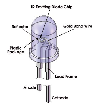 IR LEDs: These components been developed with wavelengths well into the near-IR spectrum, with continuous power outputs of approximately 1 mW and pulsed power in the tens of milliwatts for wavelengths to 2.2 μm. Higher-wavelength LEDs are available, but the power output is in the microwatt range.
To extend the wavelength range and increase the power output, pumping techniques are used whereby a lower-wavelength source (LED or semiconductor laser) is used to excite a material with a bandgap in the wavelength of interest. The excited material then emits photons at a longer wavelength. This technique can increase the output power 20 times over that of standard LEDs at wavelengths greater than 3 μm.
Laser Diodes: Because of the process of stimulated emission of photons, a laser diode has an even narrower bandwidth than a conventional LED. In addition, laser diodes can have power outputs in the milliwatt range, making them appropriate for applications that require a high-power, narrowband source. Quantum cascade lasers can produce tens or hundreds of milliwatts in pulsed mode into the far-IR.
Quantum emitters offer high speed and efficiency but are not suited for broadband spectroscopic applications. Thermal emitters are well-suited spectrally for broadband applications, with outputs closely approximating Planck’s blackbody curve. Advances in technologies such as micromachining and in applications of existing physics have led to thermal radiators that have a long lifetime as well as relatively high pulsing speeds with high modulation depth.
In addition, cost is always a criterion for any practical system, and solutions that are more exotic are more expensive, but prices will decrease as technology advance. All of these developments improve the quality of spectroscopic systems but require the designer to carefully consider the trade-offs when selecting a specific emitter technology.
Meet the author
Brian Elias is director of engineering at Cal Sensors Inc. in Santa Rosa, Calif.; e-mail: [email protected].
History
In 1860, Gustav Kirchhoff used the term “blackbody” to refer to an object that perfectly absorbs and thereby perfectly emits energy. In 1894, Wilhelm Wien developed his displacement law, which provided the general form of the equation for the spectral distribution of the radiation from a blackbody. Unfortunately, it agreed only with the experimental data at short wavelengths. In 1900, Lord Rayleigh derived an expression that fit the experimental data for long wavelengths, but his expression predicted that energy would increase without limit as the wavelength decreases, earning it the dubious distinction as the “ultraviolet catastrophe.” Max Planck interpolated between Wien and Rayleigh to provide a radiation formula that was valid at all wavelengths. He presented his paper to the German Physical Society on Oct. 19, 1900. This introduced the concept of quantum physics.