The rapid adoption of 3D NIR sensing systems requires effective methods to measure the quality, performance, and safety of NIR emitters.
ANNE CORNING, RADIANT VISION SYSTEMS
3D sensing with NIR wavelengths has taken off in the past several years, with use in such applications as facial and gesture recognition, eye tracking, and automotive vision systems such as lidar. The market for these optical sensing systems is projected to see a 22.7 to 24 percent compound annual growth rate, reaching as high as $3.8 billion in total revenues by 20271,2.
NIR wavelengths range from 700 to 1500 nm, and NIR light sources can be used for multiple applications. For example, NIR in the 780-nm range is
used and considered safe for eye tracking, the 850-nm range is used for night vision in security cameras, and emissions from 930 to 950 nm are common for the NIR LEDs in a standard television remote control. Wavelengths from 700 to 950 nm are used in a variety of NIR spectroscopy applications for medical diagnosis.
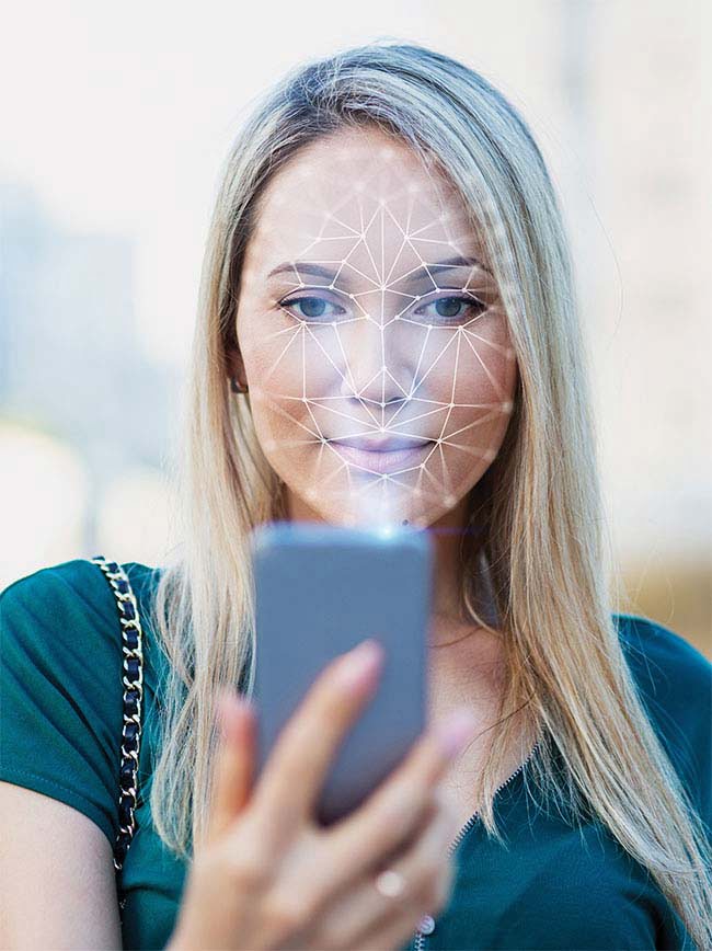
A representation of an NIR system being used for facial recognition. The smartphone emits a diffractive optical element (DOE) dot-grid pattern (invisible to the user) that is cast on the face. An IR camera inside the phone captures the reflection of NIR light and analyzes deformations of the grid pattern to determine 3D contours of the face for identification.
On a large scale, pulsed lasers in the 1040- to 1060-nm range have been used for terrestrial mapping with lidar systems. Meanwhile, developers in the automotive industry have been testing short-range (905 nm) and long-range (1550 nm) NIR wavelengths for lidar sensors in driver-assistance systems and self-driving vehicles.
IR and NIR wavelengths are commonly produced by LEDs and lasers. NIR LEDs are used in remote controls, security cameras, facial recognition devices, and medical treatments. Laser NIR wavelengths are commonly produced by vertical-cavity surface-emitting lasers (VCSELs) for applications such as optical fiber telecommunication, automotive lidar, and gesture and facial recognition.
While NIR LEDs are typically less expensive, NIR lasers offer advantages that are driving their rapid adoption, even replacing NIR LEDs for certain applications. NIR lasers are better at proximity sensing and autofocus; for example, they can be directed and reflected with greater precision for facial and hand gesture recognition. Because of their spatial coherence and focus, laser beams can pass through small openings, making them easy to integrate and manipulate through diffractive elements. Laser NIR enables 3D imaging solutions with superior depth measurement and mapping capabilities, using structured-light (projecting light in a known pattern) and time-of-flight (TOF) approaches for applications such as facial identification.
NIR and DOE
In structured-light NIR sensing, a single beam from an NIR laser is projected through an optical structure — a diffractive optical element (DOE) — to split the laser into multiple emission points and cast an array of tiny invisible dots in a grid or other fixed pattern onto a 3D object, such as a person’s face. When the light from each dot is reflected back from the object, an IR camera measures how the pattern has been deformed and interprets the reflected light (via processing software) to determine the contours of the object.
Unaffected by visible light, NIR sensors can accurately receive NIR reflections cast on a face to interpret the 3D features and contours unique to each individual. This NIR facial “map” is matched to a stored image for identification. NIR facial sensing ensures that you (and only you) have access to your personal information, bank account, car, or other protected media. Because NIR systems sense depth, they cannot be hacked with a 2D photograph, thus providing enhanced biometric security. In the field of crime prevention, NIR facial sensing can also be used to identify individuals in a crowd, allowing law enforcement to spot targets.
Time of flight
TOF methods measure the distance between a sensor and an object, based on the time difference between the emission of a signal (such as an NIR laser pulse) and when the signal’s reflection,
or backscatter, is received by the sensor. Correlating the time of the backscattered light with the time of the original illumination pulse allows the distance (d) to the object to be estimated by , where t is the TOF and c is the speed of light.
Both light and sound signals are used for TOF measurement in various applications. IR light is particularly effective for TOF measurement because it can be separated from ambient light, resulting in less signal disturbance and greater accuracy in low light or nighttime conditions. In facial recognition applications, TOF provides highly accurate depth and spatial measurement (Figure 1).
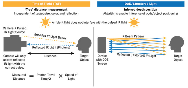
Figure 1. NIR laser 3D sensing methods. A comparison of TOF and DOE/structured-light. DOE: diffractive optical element. Courtesy of Radiant Vision Systems.
Quality considerations
With the rapid adoption of 3D NIR sensing systems comes a growing demand for effective methods to measure the quality, performance, and safety of NIR emitters. First, measuring NIR light sources requires a system capable of characterizing the typical wavelength range used by NIR applications. For facial recognition, a measurement system needs to address the 810- to 960-nm range typical for NIR sources used in these applications. While 3D NIR technology provides more accurate facial recognition than previous 2D (photographic) methods, NIR systems can still be subject to performance issues. What if the emissions of the NIR light source are inaccurate in scope or intensity? What happens when poorly placed or low-output emissions are interpreted by the sensing device?
Do all emissions meet safety standards?
To achieve device quality and performance, manufacturers must apply careful measurement and testing to their NIR sources. Ideally, a measurement system captures a variety of different characteristics, such as emission uniformity, maximum power or intensity, radiant flux, and emission distribution or spatial position, and it measures these parameters across the entire distribution area (Figure 2).
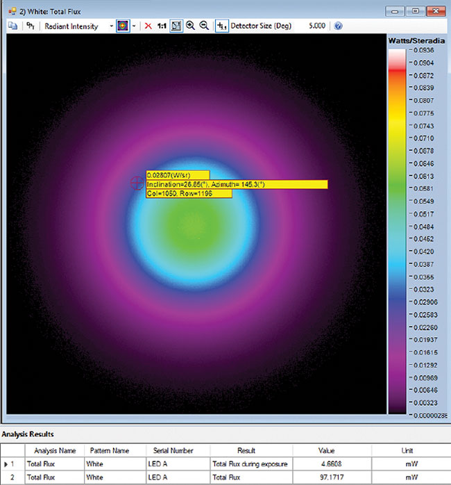
Figure 2. An example of a total flux analysis of an NIR LED over angular space, shown in a false-color scale using radiometric light measurement software. Radiant flux is a measure of radiant energy emitted per unit of time; for example, watts (J/s). Courtesy of Radiant Vision Systems.
Safety considerations
While NIR wavelengths are invisible to humans, they can still enter the eye and — with prolonged exposure — cause damage to the retina or cornea. Early automotive lidar systems were developed using 905-nm lasers, but designers have recently begun moving toward 1550 nm because humans are at risk when they are near an automobile emitting pulses at the lower wavelengths. Similarly, facial recognition and eye detection systems must be carefully designed and tested to ensure they are emitting at safe levels.
Today, the European Union, Canada, and parts of Asia require that all lights be tested and documented to the IEC 62471 standard3 to protect workers from injury caused by UV, visible, and IR/thermal electromagnetic radiation. Standards like this define thresholds for maximum permitted exposure given the source, wavelength, and intensity.
The IEC 60825-1 standard4 applies specifically to lasers, including NIR lasers. Additionally, in the U.S., the American Conference of Governmental Industrial Hygienists (ACGIH) has established the threshold limit values (TLVs) for physical agents (including lasers, light, and NIR radiation)5. These TLVs are used as a safety reference in many test reports.
Testing challenges
Beyond issues of safety, testing facial recognition systems presents another challenge for the evaluation of NIR performance. Capturing NIR light in angular space — especially when identifying the nearly 30,000 emission points produced by today’s smart device DOEs — is extremely difficult for traditional measure-ment equipment. The use of imaging NIR measurement systems, such as a CCD-based radiometric camera, for NIR source measurement can limit this complexity by capturing and measuring all emission points produced by a DOE across a large spatial area.
In order to analyze the entire emission area that will cover a face, the testing device must quickly capture and evaluate a large angular distribution at close range. A wide-angle scope is needed to accomplish this because NIR-emitting devices such as hand-held smartphones are typically positioned at a short distance.
Like any other light source, an NIR light emits light in 3D angular space. Thus, the dots in a DOE pattern may vary in intensity or position based on emission angle. Measurement of the NIR DOE pattern must be performed at each emission angle to ensure that DOE patterns are accurately projected and that each dot has sufficient intensity to be received and correctly interpreted by the device’s NIR sensor.
Angular measurement solutions
To evaluate the intensity of NIR emissions across angular space, a device manufacturer may employ a goniometric measurement system. A goniometer rotates an NIR light source in front of a
photodetector or a camera to capture 2D images of emissions at each angle. This process is time-consuming, requiring thousands of rotations to capture a complete angular measurement. Furthermore, gaps in measurement can occur between goniometric rotations, missing irregularities in NIR intensity at certain points. Because NIR emissions can be dangerous to human vision, missing any angular data point during goniometric measurement may mean missing an irregularly strong emission that could prove hazardous to the user, especially over time.
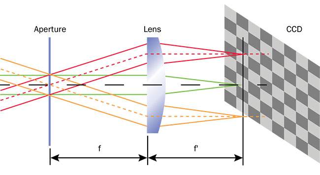
Figure 3. An illustration of Fourier optics directing angular emissions of light through a specialized lens onto points on an imaging system’s CCD, forming a 2D polar plot of the 3D distribution. Courtesy of Radiant Vision Systems.
A camera combined with Fourier optics provides an alternative to goniometers. By capturing angular emission data from a single point, it eliminates the need to rotate the device. Lenses designed using Fourier optics principles enable connected imagers to characterize the full angular distribution of a light source, leaving no gaps in measurement. Advanced NIR measurement systems such as this can characterize the radiant intensity (strength) of an entire NIR light source, identifying irregularities, peak emission, hot spots, and other issues (Figures 3 and 4).
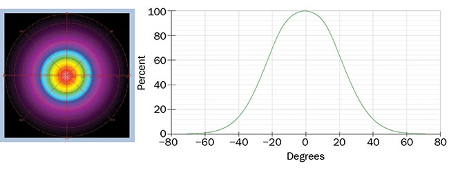
Figure 4. A radar plot and cross section showing radiant intensity (as a function of the angle) of an IR LED. Captured by a Radiant Vision Systems’ NIR Intensity Lens and shown in their TrueTest software platform for light source measurement. The Fourier-optic lens is calibrated to its connected imaging system, allowing it to accurately map angular emissions of the NIR device to ±70° at once. Courtesy of Radiant Vision Systems.
DOE measurement challenges
When evaluating NIR DOE emissions for facial recognition, it is imperative to assess every single dot for performance and safety. Until recently, the method for measuring DOE emissions was limited to checking dot patterns for accuracy by mapping them against ideal patterns or coordinates (typically with the source cast against a screen or a wall). Because this method is simply a static pattern match, however, it does not dynamically adapt to new DOE patterns. Nor can this method report precise radiometric data of the DOE emission points, because it provides only dimensional evaluation and simple pass/fail analysis.
Each dot in a facial recognition DOE array must be accurately positioned (angle, inclination, azimuth) and emitted with the correct radiant intensity (measured in watts per steradian, W/sr)
to ensure it is properly reflected back and “understood” by the device’s IR sensor. Manufacturers must control the position and output of each dot for the device to map facial contours correctly. For thorough evaluation of dot-by-dot performance and safety, the ideal system should identify points of interest across the image, measure values for each dot in the DOE pattern, and evaluate the accuracy of the pattern as a whole (Figure 5).
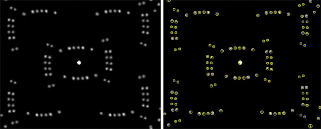
Figure 5. A sample DOE dot pattern before (left) and after (right) analysis using automatic dot detection in TrueTest software. The software measures maximum peak (strongest emitter), maximum peak location (inclination/azimuth), maximum peak averages, maximum peak solid angle, number of pixels as maximum peak point, spot-power uniformity (between dots), total and DOE flux, along with dot-by-dot measurements. Courtesy of Radiant Vision Systems.
Flood measurement considerations
Some facial recognition systems rely on a flood function, which is a strong flash of NIR light used to detect the presence of a face and determine focus distance, even in darkness. Like all NIR emissions, this flood function must also be tested to ensure it adheres to defined safety and performance parameters. For example, irregularities such as hot spots or a fall-off of intensity around the perimeter need to be identified and corrected (Figure 6).
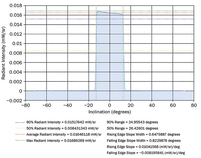
Figure 6. An example of a flood sample cross section derived from Radiant Vision Systems analysis software. Courtesy of Radiant Vision Systems.
Conclusion
Effective approaches to testing product quality are required to ensure the performance and safety of a new generation of 3D sensing devices that use NIR emitters.
Applications used on and around humans — such as eye tracking, facial recognition, medical treatment, and automotive lidar — require the most rigorous safety testing to comply with industry standards. Advances in NIR testing using radiometric measurement systems and specialized Fourier optics are helping to address this need, enabling fast and precise evaluation of radiant intensity, power, flux, and dot-by-dot characterization of DOE patterns.
Meet the author
Anne Corning is a content writer at Radiant Vision Systems, a leading manufacturer of photometric and radiometric imaging solutions for light and color measurement; email:
[email protected].
References
1. Yole Développement. (April 2017). IR LEDs and VCSELs — technology, application and industry trends, https://www.slideshare.net/Yole_Developpement/ir-leds-and-lasers-technology-applications-and-industry-trends-2017-report-by-yole-developpement.
2. LEDinside (TrendForce). (March 2017). 2017 IR LED/IR laser and optical sensor market report, https://press.trendforce.com/node/view/2765.html.
3. International Electrotechnical Commission (2006). IEC 62471, Photobiological safety
of lamps and lamp systems, https://webstore.iec.ch/publication/7076.
4. International Electrotechnical Commission (2014). IEC 60825, Safety of laser products, https://webstore.iec.ch/publication/3587. Reinforced by FDA Draft Guidance
(Jan. 2018), https://www.fda.gov/downloads/medicaldevices/deviceregulationandguidance/guidancedocuments/ucm592775.pdf.
5. ACGIH (2001). Documentation of the threshold limit values for physical agents, 7th ed., with 2002-2018 Supplements, https://www.acgih.org/forms/store/ProductFormPublic/documentation-of-the-threshold-limit-values-for-physical-agents-7th-ed.