A z-splitter prism collects information from many focal planes and, through the use of an advanced algorithm for removing out-of-focus blur, provides high-contrast 3D images in a single shot.
SHENG XIAO, BOSTON UNIVERSITY
Optical microscopes use light to visualize detailed structures of small samples. The most popular microscopy technique for biological or biomedical studies by far is wide-field microscopy, in which a sample, such as tissue, is imaged through a digital camera. Because this technique is easy to use, low noise, minimally invasive, and applicable to a variety of sample conditions — such as being immersed in water or exposed to air — it is one of the most commonly used tools for medical and biological studies. With recent advancements in high-speed, large-area image sensor technologies, a modern wide-field microscope is able to offer high-resolution images across a large field of view at very high speed.
However, a fundamental trade-off in the use of optical microscopes is the relationship between image resolution and depth of field1. Users can typically observe sharp sample details only within the microscope’s focal plane, whose thickness depends on the depth of field. And the finer the details a user wishes to see, the thinner the focal plane will be after adjusting for adequate resolution. All out-of-focus sample information will become irreversibly blurred in the image.
A team at Boston University devised a technique to collect information from many focal planes at once, aided by a special algorithm for removing out-of-focus blur that may clear these hurdles in modern research. The work could assist in a number of biomedical applications and in the study of dynamic systems.
While many biological samples are 3D in nature, only a thin 2D plane is observable at any one time in traditional microscopy. A simple way to obtain full 3D information is to sequentially record images at each focal plane by translating the sample or the microscope objective, a capability available in many commercial microscopes. But, of course, this strategy comes at the cost of increased acquisition time. And in many situations, such as when studying live or freely moving animals — where imaging speed is critical — it is desirable to record 3D information at the native camera frame rate without sacrificing speed.
Several techniques have been proposed to obtain a 3D image of the sample in a single shot. One well-known piece of equipment is a light-field camera2, in which a lenslet array is used to capture both the directions and positions of light rays. This information is then used to computationally reconstruct a 3D volume.
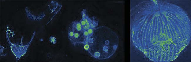
Volume dark-field imaging of various samples. By using a nine-plane z-splitter prism, an entire sample can be imaged in a single shot. Extended depth-of-field images of radiolaria, volvox, and dictydium (left to right). Courtesy of Sheng Xiao.
Although the technique is very simple, satisfactory 3D reconstruction generally requires sample sparsity, or data that is spread out across the focal plane. When imaging thick or densely labeled samples, a loss of image contrast can result from the poor focus of the lenslet array. In such cases, a multifocus strategy, in which a series of distinct focal planes are recorded simultaneously, may be a better solution. This can be achieved by using multiple detection cameras, each one targeting a single focal plane, or, more practically, by using a single camera to simultaneously record all focal planes. For the latter option, an optical device is required to convert axially distributed focal planes into laterally separated images that can be projected onto a common image sensor.
To date, examples of such devices that provide multiple detection points include specially fabricated beamsplitters3 (using two detection cameras) or diffractive optical elements4. Both of these examples are typically difficult to design and manufacture. The former requires the fabrication of custom-shaped beamsplitters, and the latter requires electron-beam lithography to make custom patterns on a glass substrate. In addition, the application of these devices has been limited mostly to superresolution imaging and single-particle tracking over a small 3D field of view. The devices are unable to study more complex 3D biological organisms and systems.
Z-splitter prism
The technique for simultaneously acquiring images at various depths that was developed by the researchers at Boston University used a standard microscope5. The core component of the technology is a device called a z-splitter prism (Figure 1), by which the detected light is split into several paths, with increasing optical path delay to the sensor. Each path corresponds to an image from a different depth in the sample, with all of them directed onto a common camera. Using a high-speed camera with a large sensor area and high pixel count, all of the images can be recorded simultaneously without overlap, essentially capturing information in full 3D volume in a single camera snapshot.
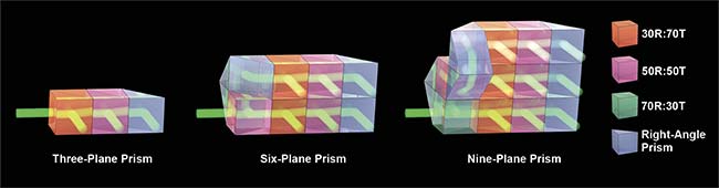
Figure 1. The design of a z-splitter prism. Various designs can be considered for three-, six-, or nine-plane imaging. R: reflection; T: transmission. Courtesy of Sheng Xiao.
The z-splitter prism itself was constructed by cementing various parts of partial beamsplitters and right-angle prisms together, so that the output of each beamsplitter prism represents a distinct focal plane. Various designs can be considered, each offering a different number of focal planes. The simplest one is a three-plane prism, consisting of a 30R:70T beamsplitter, a 50R:50T beamsplitter, and a right-angle prism. The beamsplitting ratio is chosen so that roughly one-third of the total power exits from each beamsplitter or prism.
A more complex six-plane prism can be assembled by splitting the detection light into two paths using a single 50R:50T beamsplitter, with one beam optical path length extended longer for the length of three beamsplitters. Each path is subsequently split into three images using a three-plane prism, therefore creating six independent images focused at various depths. Similar design principles can also be applied to create a nine-plane prism, in which three three-plane prisms are used to generate images from nine distinct focal planes. Since all of the beamsplitters and right-angle prisms used are standard off-the-shelf components and have the same dimension, the z-splitter prisms can be easily assembled in the lab without complicated machinery.
High-contrast deconvolution
Although a z-splitter prism allows the observation of multiple focal planes simultaneously, signals from out-of-focus structures are still present in the recorded images. This may not pose a problem for thin transparent samples. But when imaging thick or densely labeled samples in 3D, such out-of-focus blur reduces the image contrast, making it more difficult to distinguish in-focus features from blurry background.
Luckily, the 3D nature of the image acquisition with a z-splitter prism can be exploited to suppress the out-of-focus background, thereby improving the image contrast and signal-to-noise ratio. The technique used here is called image deconvolution, in which image blur is removed by inverting the blurring process with the knowledge of point spread function. This function determines how a point object will be blurred when it is imaged through the camera. In the case of a z-splitter prism, the blur will be present in images across all depths, but to varying degrees. Such a feature allows users to accurately estimate the amount of blurring and to reassign the blurred signals back to the original sources. The process essentially removes the out-of-focus blur. This deconvolution procedure has been well established by a widely adopted algorithm called the Richardson-Lucy deconvolution.
However, the difficulty in using such traditional deconvolution algorithms is in removing far-out-of-focus blur — that is, signals that originate from sources outside the actual imaged volume. This often happens when imaging thick samples, such as mouse brains, in which only superficial layers are being imaged, while at the same time out-of-focus signals are coming from much deeper layers of the brain.
To solve this problem, a new deconvolution strategy called extended-volume 3D (EV-3D) deconvolution was developed, in which far-out-of-focus blur is explicitly considered in calculations. This is achieved numerically by extending the 3D image volume both axially and laterally and then estimating both the image data within the extended volume and the deblurred object via an iterative procedure called alternating minimization. The process leads to a higher image contrast and much better background suppression of far-out-of-focus signals (Figure 2).
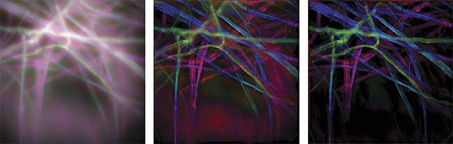
Figure 2. A color-coded 3D image of a fluorescent lens paper. The various colors represent different depths. The original image before deconvolution, the image deconvolved via a traditional algorithm, and the image deconvolved via the extended-volume 3D (EV-3D) algorithm (left to right). Courtesy of Sheng Xiao.
3D biomedical platform
With a z-splitter prism, any camera-based microscope can be adapted for single-shot 3D imaging. As a result, a wide range of biological samples with different contrast mechanisms can be imaged, enabling various kinds of biomedical studies. For example, a neuroscientist can use the prism as a fluorescent microscope to study the function of brain neural networks. Thanks to the nonscanning nature of 3D acquisition, fast neural activities and signal propagations can be recorded by imaging large ensembles of neurons in 3D (Figure 3). After deconvolution via the EV-3D algorithm, image contrast and signal-to-noise ratio can be improved to facilitate any further signal extraction and analysis algorithms.
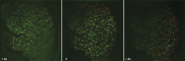
Figure 3. The in vivo fluorescent imaging of neural activities in a live mouse brain. Individual neurons across three focal planes can be imaged simultaneously. Activities from more than 500 neurons can be tracked in real time. Courtesy of Sheng Xiao.
When using the prism with a microscope in the phase-contrast configuration, small organisms such as rotifers — a microscopic marine species that is important in the research of aging and ecology — can be imaged while behaving in their natural state. Also, dark-field imaging (see opening image) can be augmented to multiple focal planes, enabling users to image an entire small animal with a single picture, to assist in studies such as the hemodynamic monitoring of water fleas for bioassays. Other modalities such as hyperspectral or polarization imaging are also possible with this method.
The z-splitter prism is also flexible when trading off imaging volumes for speed. The z-splitter comes in various designs — by which users could image three, six, or nine planes — with each design offering a different image geometry. While a three-plane prism offers an elongated 1 × 3 image geometry, a nine-plane prism offers the largest imaging volume demonstrated to date — a square 3 × 3 geometry. And a six-plane prism offers a compromise between the two. All of these designs can be swapped on site to prioritize either higher imaging speed or larger imaging volume.
A common feature in modern CMOS cameras is the rolling shutter readout structure, in which an image is read line by line from the sensor, and a faster frame rate can be achieved if an image has fewer lines to read out. Therefore, with a three- or six-plane prism, users can take advantage of such a feature by cropping the sensor area to an elongated aspect ratio, enabling high-speed imaging beyond the native frame rate of the camera. This would be helpful for imaging fast 3D dynamics, such as rotifer cilia, which beat every hundredth of a second. With a moderate-speed camera that runs at 30-Hz full frame rate, such dynamics can be easily resolved by imaging at 100 Hz using an elongated six-plane prism (Figure 4).
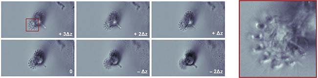
Figure 4. The beating cilia of a living rotifer. Six focal planes can be imaged simultaneously at 100 Hz without motion blur. Single-shot imaging of six focal planes (left). A zoomed-in view of the rotifer cilia (right). Courtesy of Sheng Xiao.
To explore the full potential of a z-splitter prism, researchers are working on adapting the technology for more imaging modalities, so that an even wider range of samples could be visualized in 3D. Hopefully, a standard wide-field microscope with a simple z-splitter prism add-on will become a general platform for high-speed, high-contrast, large-field-of-view 3D biomedical imaging applications.
Meet the author
Sheng Xiao is a postdoctoral researcher at the Biomicroscopy Lab of Boston University. He received his doctoral degree in electrical engineering from Boston University; email: [email protected].
References
1. J. Mertz (2019). Introduction to Optical Microscopy, 2nd ed. Cambridge, England: Cambridge University Press, www.doi.org/10.1017/9781108552660.
2. R. Prevedel et al. (2014). Simultaneous whole-animal 3D imaging of neuronal activity using light-field microscopy.
Nat Methods, Vol. 11, pp. 727-730.
3. A. Descloux et al. (2018). Combined multi-plane phase retrieval and super-resolution optical fluctuation imaging for 4D cell microscopy. Nat Photonics, Vol. 12,
pp. 165-172.
4. S. Abrahamsson et al. (2013). Fast multicolor 3D imaging using aberration-corrected multifocus microscopy. Nat Methods,
Vol. 10, pp. 60-63.
5. S. Xiao et al. (2020). High-contrast multifocus microscopy with a single camera and z-splitter prism. Optica, Vol. 7, Issue 11,
pp. 1477-1486.