When faced with the limits of traditional AR coatings, metasurfaces with moth-eye features can offer useful alternatives to a power-hungry fiber optics industry.
DEVINDER SAINI AND RON MEHL, FIBERGUIDE INDUSTRIES INC.
The use of optical fiber in astronomy, biomedical instrumentation, communications, defense, digital projection, industrial laser, medical, and sensing applications has increased over several decades to the point that it is now almost ubiquitous. Among its many functions, optical fiber delivers high optical power and detects very low intensity signals. Regardless of the application, however, a generally unwanted reflection from the end face of the fiber causes problems.
It is a weak reflection from the front and back surfaces of the glass and is similar to the type one sees when looking out a window. The reflection is due to light moving from one medium to another with some light reflected from the surface. Its magnitude depends upon the ratio of the refractive indices of the two media and the angle of the surface relative to the light beam, and it is calculated using the Fresnel equations. Typically, for glass in air, 4% of the light is reflected, and for many applications this reflection is problematic. With high power, reflections can cause damage. With low power, they can reduce the light transmitted. The problem is normally lessened with antireflection (AR) coatings.
When the light meets the interface at normal incidence, the intensity of light reflected is given by the reflectance, R, and where n0 and ns are the refractive indices of the first and second media, respectively:
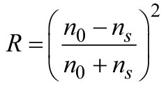
This equation shows that increasing the refractive index difference leads to increasing reflectance. Alternatively, reflectance can be reduced by decreasing the refractive index difference.
The AR properties of coatings on optics were first discovered by Lord Rayleigh around 1886 when he found that a thin film on the surface of glass reduced reflection and increased transmission. In an experiment, the AR effect was achieved by varying the refractive index of the film so that it measured between that of glass and air. Therefore, using a film with a refractive index of 1.225 will reduce the reflection from glass from ~4% to 1% at each interface.
Over the years, AR technology has been refined and become quite sophisticated, with multilayers used to produce a gradual change in the refractive index and to produce an interference effect. Today, some of the best AR coatings can reduce reflectivity to less than 0.1%. Due to the multilayer nature of the coatings, however, such low reflectivities are achieved across only a few nanometers, and the coatings are angle dependent. Nevertheless, these AR coatings are used in almost all applications with optics, including cameras, eyeglasses, and optical fibers.
More power, more problems
Conventional AR coatings with a low damage threshold have limitations in a fiber optic industry with ever-increasing demands for power delivery. For example, when launching light into a fiber, the optical beam is focused down to a small spot with a numerical aperture (NA) below or matching that of the fiber. This spot, however, must be smaller than the diameter of the fiber core to allow for efficient coupling. With a reduction in spot diameter, the energy density quadruples and leads to damage in the AR coating, rendering it unusable (Figure 1).
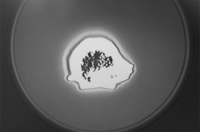
Figure 1. Laser-induced damage on an AR coating on a fiber end face. Courtesy of Fiberguide Industries.
The damage occurs at the glass interface and can be mitigated with end caps. Because of the significantly higher damage threshold of light traveling in glass, high-power light can be launched into fiber through an end cap. The size of the focused spot on the end cap can be larger at the glass/air interface and hence have a lower energy density, while the spot at the end cap/fiber (glass/glass) interface is smaller than the diameter of the fiber. The use of end caps on fibers has enabled the optical power delivered to increase, by effectively allowing for a larger spot size at the launch face of the fiber (Figure 2); however, AR films are still required to reduce reflections.
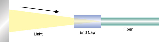
Figure 2. Light focused on the end of a fiber through an end cap. Courtesy of Fiberguide Industries.
Damage thresholds for AR films have effectively been reached. Clearly, there is a need for a more robust solution — one that reduces reflections from the fiber end face, has a much higher damage threshold, and has (ideally) a much broader operating window than multilayer AR films.
Moth-eye structures
Better outcomes have been achieved
by adding metasurfaces to the ends of fibers, replacing standard AR coatings. These surfaces, which replicate the structures of moth eyes, impart AR properties to the end faces of the fibers and are superior to traditional coating solutions in almost every way: They have superior
damage threshold, they work over a broad
wavelength range with no angular dependence, and they can be used in both high- and low-power applications.
The eyes of moths and other insects have an interesting property: They do not exhibit any reflections. When viewed under a scanning electron microscope, their eyes have tiny structures at the nanometer scale (Figure 3).
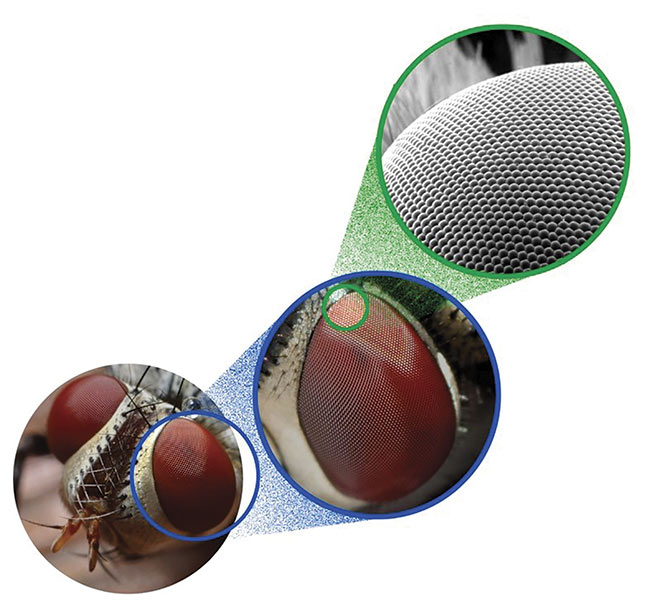
Figure 3. A close-up of an insect’s eye. Courtesy of Fiberguide Industries.
During the 1960s, it was discovered that corneal lenses on insects such as moths have periodic cone-like nanostructures that reflect very little light at any wavelength or incidence angle1. It was also discovered that the low reflectance was due to the continuous refractive index
transition between air and the substrate (cones on the eye). Therefore, if the surface of a substrate could be produced with cone-like structures, the reflection could be reduced. The size of the structures affects the reflection properties. Typically,
these structures are smaller than the wavelength of light. The lower wavelength limit is determined by the lateral size of the structures, and the upper wavelength limit is determined by the depth.
A technique based on moth-eye structures has been developed to provide AR properties for glass and is now being applied to optical fiber end faces.
Further work by Douglas S. Hobbs and colleagues has shown that random nanostructures rather than ordered structures produce even better AR properties2.
Random antireflection surfaces
Random nanostructures are created with reactive ion plasma etching techniques on glass surfaces. These structures mimic moth eyes and have AR properties.
A laser-induced damage threshold (LIDT) of 42.6 J/cm2 has been reported by Hobbs and colleagues3 on fused silica (Corning 7980) windows with random antireflection (RAR) structures at
1064 nm with 20-ns pulses and a spot size of 0.5 mm, compared to untreated fused silica, which has a damage threshold of 40.2 J/cm2.
These tests were repeated using the same type of Corning fused silica that was plasma-etched to produce RAR structures, and this time it was AR-coated (coating manufactured by San Jose, Calif.-based Cascade Coatings) with the most robust AR coatings. These samples were sent to an independent test lab,
Quantel Laser, for LIDT testing. The samples were tested at 1064 nm with 16-ns pulse width, 0.371-mm spot diameter, and a repetition rate of 20 Hz. The results were very similar to those obtained by Hobbs and colleagues. The damage threshold for AR-coated samples was 24 J/cm2 and for plasma-etched RAR structures was 48 J/cm2.
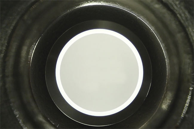
Figure 4. A photo of an etched fiber in an SMA connector (a), and a scanning electron microscopy (SEM) image that shows the structures in detail (b). Courtesy of Fiberguide Industries.
RAR on optical fibers
Optical fibers with 1500-μm cores were etched to create RAR surfaces on their end faces (Figure 4). The etching process produced fiber end faces with reflectivity of <0.1% over a broad wavelength band of 800 nm (Figure 5). These fibers (along with untreated and AR-coated fibers) were sent to Quantel for LIDT measurements using the same setup that was used for the fused silica windows. The results showed damage thresholds of 130 J/cm2 for the untreated fiber, 59.1 J/cm2 for the etched RAR fibers, and 27.7 J/cm2 for the AR-coated fibers (Figure 6). The AR coating was centered at 1064 nm with a reflectivity of 0.04%.
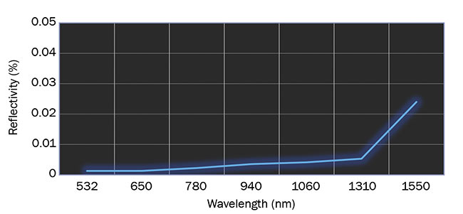
Figure 5. Reflectivity from an etched fiber end face. Courtesy of Fiberguide Industries.
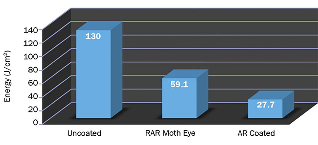
Figure 6. Laser-induced damage threshold for uncoated fiber, fiber with a RAR moth-eye surface, and fiber with AR coatings. Courtesy of Fiberguide Industries.
RAR (meta) surfaces vs. AR coatings
The results so far show that the RAR structures produce AR properties that are superior to those shown by conventional AR coating. RAR surfaces have a bandwidth of several hundred nanometers, with a damage threshold that is twice that of AR films. This makes the RAR moth-eye structures eminently suitable for high-power applications where AR coatings cannot be used.
These surfaces can reduce reflectivities well below those achieved by AR coatings, with a very broad operating range of wavelengths and no angle dependence. They can be used in applications such as flow cytometry, where detecting very low levels of light over a broad band is essential.
Meet the authors
Devinder Saini, Ph.D., is vice president of technology at Fiberguide Industries Inc. He has a doctorate in physics, holds nine patents, and has over 50 publications in the field of sensors in a variety of industries; email: [email protected].
Ron Mehl is development engineer and
marketing specialist at Fiberguide Industries Inc. He has worked in the fiber optic industry
for more than 30 years and is based in Caldwell, Idaho; email: [email protected].
References
1. C.G. Bernhard and W.H. Miller (1962).
The insect corneal nipple array. Acta Physiol Scand, Vol. 56, p. 385.
2. D.S. Hobbs et al. (April 2007). Update on the development of high performance anti-reflecting surface relief micro-structures. SPIE 6545-34.
3. D.S. Hobbs and B.D. MacLeod (September 2007). High laser damage threshold surface relief micro-structures for anti-reflection applications. SPIE 6720-68.