
Motion Control Solutions for High-Precision, Large-Field Laser Micromachining
Demanding laser processes will benefit from a control mechanism that enables improved throughput and accuracy.
SUSANNE ABL AND JOHN FLEMMER, SCANLAB GMBH, AND JASON GOERGES, ACS MOTION CONTROL INC.
High-precision, high-throughput laser micromachining typically requires galvo scan heads with a short focal length, which in turn produces a small image field, or field of view (FOV). However, a growing number of high-tech manufacturing areas, such as OLED display fabrication, require the processing of workpieces larger than can fit into these reduced image fields, while simultaneously requiring a high level of accuracy and throughput. The same applies for many other laser micromachining applications, such as two-photon polymerization or the processing of glass, foils, and films. Although high precision can be achieved by using a stationary laser and a moving mechanical stage, throughput will be low. Throughput is increased when the motion of a galvo scan head is combined with motion stages to produce the desired contour of the laser beam on the processed workpiece. With this approach, the micromachining process field area will be limited only by the travel range of the stages, and throughput will not be compromised.
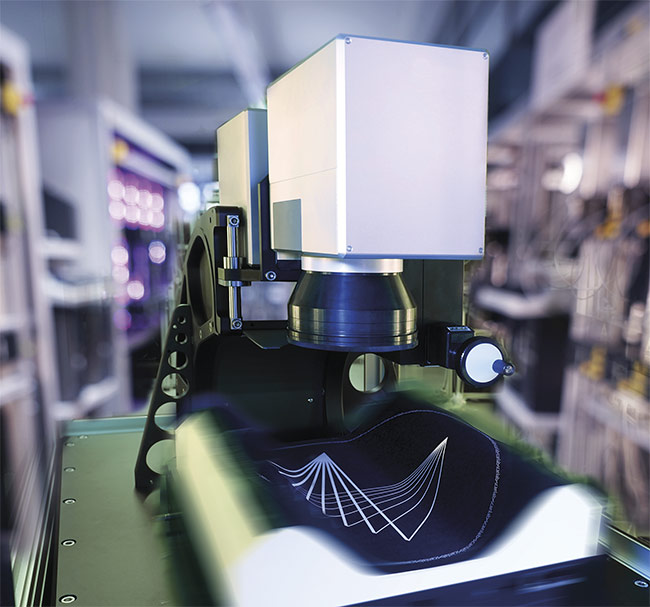
Combined galvo and stage control solution for processing three-dimensional and large workpieces. Courtesy of SCANLAB and ACS Motion Control.
Combined galvo and stage control solutions have been available in the marketplace for several years; however, these solutions are limited in either the level of throughput or the accuracy achieved. A new approach to addressing these shortcomings combines galvo and stage control, while leveraging unique galvo scan head and motion control technologies. This solution splits the motion path in an innovative way into one path for the scan head and one for the stage and delivers them to the corresponding controller. This new system has been successfully used in demanding real-world applications to achieve improved levels of throughput and accuracy.
Novel architecture
The performance of a combined galvo and stage control solution is fundamentally dictated by: 1) how well the control system can command and control (i.e., minimize the tracking error of) its fundamental components — the galvo scan head axes and the motion stage axes; and 2) the degree to which the motion of the laser beam by the galvo and the motion stage can be synchronized.
With these concepts in mind, it becomes possible to design a control architecture (Figure 1). In this architecture, the user provides the desired contour of the laser spot on the workpiece to the software package running on the PC. This path is then processed by the decomposition algorithm of the software to generate a set of two coupled motion trajectories — one for the scanner and one for the stage — with rates of 100 kHz. These trajectories are constructed so the scan head axes and the stage axes execute the high-dynamic and low-dynamic parts of the contour, respectively. All axes realize the highest velocities and accelerations, without exceeding physical constraints, to allow for optimal throughput. The two trajectories are simultaneously fed to the galvo controller and the stage controller via the protocol converter — which converts SL2-100, a high-speed digital communications protocol, to EtherCAT — each applying innovative control algorithms that minimize their respective tracking errors.
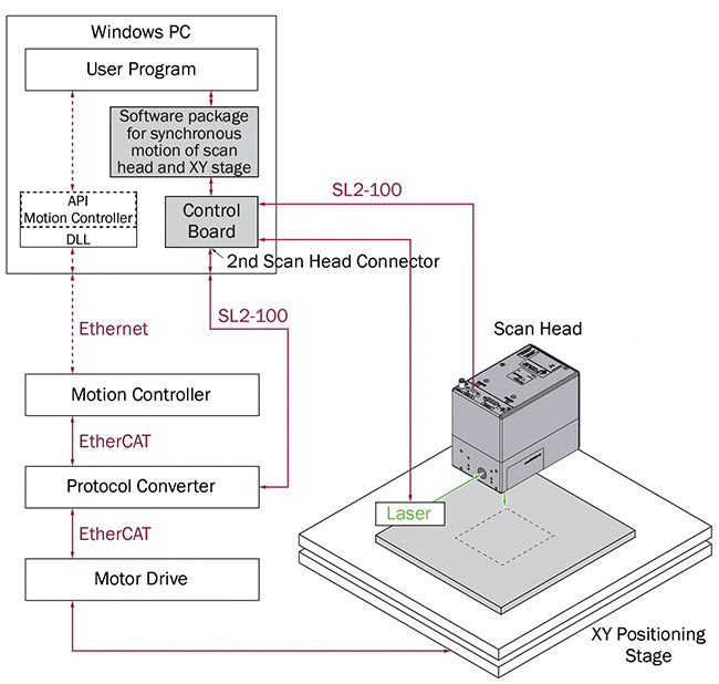
Figure 1. A scheme of the control architecture where the scanner controller is master. Courtesy of SCANLAB and ACS Motion Control.
An algorithm in the stage control subsystem can recognize deviations from ideal operation in the motion of the stage, identify the root cause of such deviations, and compensate for them, all in real time. Additional advanced feedback control, feedforward control, and mechanical accuracy compensation algorithms work in unison, enabling the motion stage to achieve submicron tracking errors at speeds of 1 m/s and accelerations of 1 G
or more. The scanner controller minimizes the scan head’s tracking errors using advanced look-ahead control. The trajectory is adapted, taking all dynamical limitations into account. When combined
with a specialized control for the galvanometer motors, the result is optimal accuracy and performance.
To validate the achievable accuracy, a grid pattern was marked (30 × 30 crosses) using the total traveling range
of the table (300 × 300 mm) and a scan head with a focusing lens of 100-mm focal length. With a mark velocity of
300 mm/s, an absolute, radial process
accuracy of 2 µm was achieved.
To summarize, optimal large-field laser micromachining throughput and accuracy is achieved by combining and synchronizing the motion of the stage with that of the scanner and using the highest-dynamic motion trajectories possible to achieve negligible stage, scan head, and overall system tracking errors.
Micromachining quality improves
In addition to the high-precision trajectory planning, control software can enable exact spot placement with modern ultrashort-pulse (USP) lasers. The specific execution of processing patterns is highly user-configurable. For example,
an operator can specify trajectory parameters for the pulse rate, for the fluence of individual laser spots, and for tolerable rounding of corners in the process image. Often processes require constant, controllable laser pulse spacing on the workpiece. Conventional pulse control systems rely on estimation to extrapolate the position, resulting in physically limited resolution (Figure 2). In contrast, trajectory planning offers advantages: Path execution without tracking errors enables placing of laser pulses precisely along the scan path to achieve the desired pulse spacing (Figure 3).
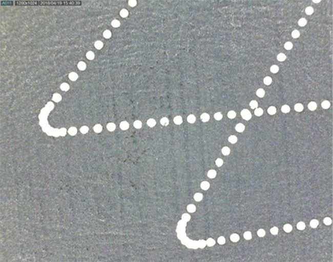
Figure 2. A process path without trajectory planning. Courtesy of SCANLAB and ACS Motion Control.
The control of the spot distance is realized using powerful hardware (here an FPGA, or field-programmable gate array, is used), resulting in a resolution of 15 ns. For a laser frequency of 500 kHz, this means achieving a maximal pulse interval deviation of 1.5% under optimal system conditions. Figure 2 shows the process path of a conventional system, whereas Figure 3 illustrates the superiority of using trajectory planning to support control.
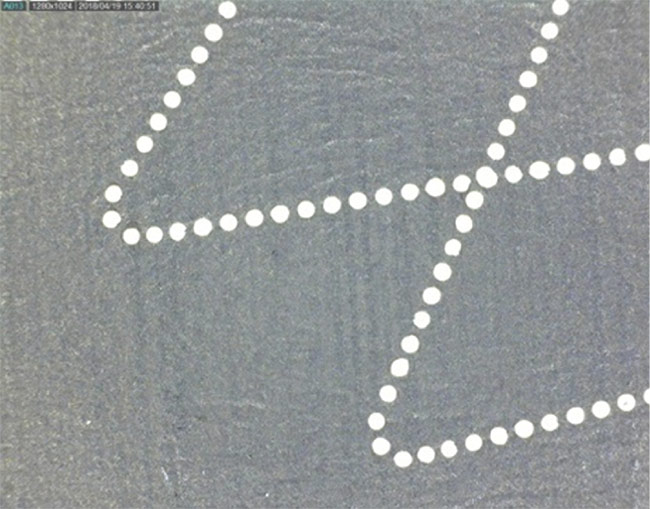
Figure 3. Constant laser pulse spacing thanks to constant pulse distance and trajectory planning. Courtesy of SCANLAB and ACS Motion Control.
Exact edges, consistent processing
Particularly in cutting applications, constant pulse spacing is essential for
the process result and the quality of the cutting edge. Many laser systems with pulse control only allow definition and control of intervals between two pulses
in relation to their midpoint. With the new pulse control solution, including trajectory planning, laser pulse intervals can
be adjusted not only to the laser path
centerline, but also to the inner or outer contour. This ensures smooth energy deposition and precisely processed work-
piece edges (Figure 4). For sensitive workpiece materials (e.g., films), the method avoids scorching and inhomogeneities.
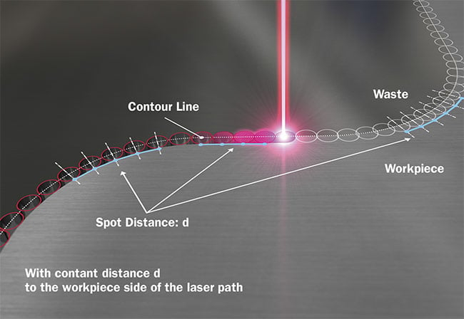
Figure 4. Equidistant laser pulses along the workpiece edge. Courtesy of SCANLAB and ACS Motion Control.
The laser’s spot size at the workpiece depends on the laser beam’s deflection angle through the scan head, although
telecentric objectives minimize this effect. Trajectory planning can adjust the laser parameters depending on the deflection angle. This enables, for example, a
constant energy density even though the
spot size varies minimally along the laser
path (Figure 5). This function can be helpful in situations such as when
homogeneous processing is needed on thin films and materials.
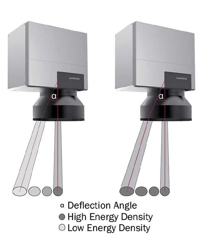
Figure 5. The relationship between deflection angle and spot size. Courtesy of SCANLAB and ACS Motion Control.
Enhanced throughput
Advanced trajectory generation not only improves process accuracy, it also exploits the system’s maximum dynamics, combined with user-specifiable tolerance limits. By using trajectory planning, inactive periods are minimized as well. Conventional systems insert acceleration phases in which the laser is switched
off before each segment to be processed; this is called the “skywriting” function.
It ensures a constant speed during processing, but it leads to increased nonproductive time. In contrast, trajectory planning reduces skywriting usage, while taking physical constraints and defined tolerances into account, so that a system-
dependent, time-optimal path can be
calculated. Thus, unnecessary acceleration times along complex laser paths are avoided, thereby boosting effective throughput.
The control solution presented here combines an EtherCAT network-based stage control subsystem and a scanner control subsystem based on a high-speed digital communication protocol (SL2-100). These subsystems are scalable, with the possibility of using multiple scan heads on one mechanical stage or
on multiple stages.
Parallelization of process steps raises throughput and reduces costs. Arrangement of the scanners is flexibly configurable. In addition to the adjustable positioning (Figure 6), it is also possible to mount four scanners adjacent to one another on a bridge. All scan heads are exactly synchronized, ensuring the overall precision of the system. This layout
allows simultaneous processing of multiple workpieces. The user gains the ability to individually adjust the orientation
of each workpiece for each scan head. This enables the user to apply automated detection (e.g., image recognition) of
the workpiece positions and orientations. By using additional mechanical axes, even the spacing between scan heads
can vary.
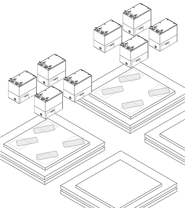
Figure 6. A multihead system. Courtesy of SCANLAB and ACS Motion Control.
System configurations with multiple scan heads are attractive for processing large-format materials, such as for fabricating touch displays. A technological shift from liquid crystal displays (LCDs) to organic light-emitting diodes (OLEDs) is in progress, and this transition requires new fabrication methods. Here, laser
cutting will offer significant advantages: The cutting edges can be created with higher precision at a higher throughput, accompanied by flexibility in product size.
Software benefits
While the motion decomposition is performed automatically as part of trajectory planning, the synchronized stage and galvo control solution presented here behaves like a conventional galvo scanner with an extra-large image field. The trajectory planning is mainly driven by software and is therefore flexible and extendable. This reduces time to market and lets machine integrators easily adapt their system to the synchronized stage and galvo control solution. At the same time, the motion controller of the stage can be used to control external peripherals or other drives.
Optimal performance and accuracy are achieved using look-ahead trajectory
planning algorithms and individually optimized control technology for mechanical axes and galvo motors. By using multiple scan heads, the throughput can be multiplied without losing accuracy. Additional features, such as the control of spot distance, give the user full control over process conditions and lead to high-quality processing results. Despite the complexity of the setup, the system can be programmed like a single laser scanner, making it even easier to get started.
Meet the authors
Susanne Abl is project and product manager
at SCANLAB GmbH for XL SCAN. She has a degree in optoelectronic engineering. During her career, Abl has gained experience in the fields of medical laser applications, laser-scanning microscopy, and laser development.
John Flemmer, Ph.D., is a technical project manager at SCANLAB GmbH and has 10 years of experience in the field of lasers and the associated machine control and software technology. He studied physics and holds a doctorate in mechanical engineering.
Jason Goerges joined ACS Motion Control Inc. in 2007 and is the global vice president of marketing, as well as North American general manager. He has a master’s degree in electrical engineering and is currently pursuing a master’s in management of technology.
/Buyers_Guide/ACS_Motion_Control_Inc/c138
Published: September 2019
Glossary
- positioning
- Positioning generally refers to the determination or identification of the location or placement of an object, person, or entity in a specific space or relative to a reference point. The term is used in various contexts, and the methods for positioning can vary depending on the application.
Key aspects of positioning include:
Spatial coordinates: Positioning often involves expressing the location of an object in terms of spatial coordinates. These coordinates may include dimensions such as...
Motion Controlmicromachininglaser micromachiningOLED displaysmotion stagesgalvo scan headsgalvo controllersstage controllerstrajectory planningskywritingscan headspulse control systemsFeaturespositioning