
Multifield Imaging Enhances Detectability at Speed
Multiarray CMOS sensors combined with wafer-level coated dichroic filters enable simultaneous capturing of bright-field, dark-field, and backlight images in a single scan.
XING-FEI HE, TELEDYNE DALSA AND SUNGHO HUH, ENVISION
Multifield imaging is a new imaging technique that enables the simultaneous capture of multiple images under various lighting conditions. Coupled with time delay integration (TDI), this emerging imaging technique can overcome many of the limitations of traditional approaches.
As conventional vision technology has become increasingly sophisticated, it has found increasingly broad application in multiple end markets, such as factory automation, environmental monitoring, and the life sciences (Figure 1).
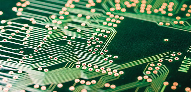
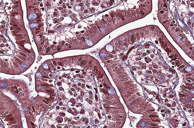
Figure 1. Emerging multifield imaging techniques capture multiple images under various lighting conditions to improve detectability in a growing array of end markets. Courtesy of Teledyne DALSA.
Line-scan cameras have become a particularly key imaging technology for applications that demand high sensitivity and fast image capture. Unlike area-scan cameras, line-scan cameras use one-dimensional linear arrays. This allows fast transfer of image data from the sensor to the camera and then to the host computer at speeds reaching hundreds of kilohertz.
In high-speed imaging, sensitivity plays an important role in achieving a higher signal-to-noise ratio and therefore better detectability to identify objects of interest. The sensitivity of a sensor depends on its quantum efficiency and photon collection capabilities, which is where time delay integration becomes relevant.
Based upon line-scan imaging techniques, time delay integration has become a proven technology for high-speed imaging in light-starved conditions1. TDI uses multiple exposures to collect more photons while maintaining low read noise. More and more high-speed applications today require time delay integration, especially if increasing light intensity on the imaged object is not an option.
In imaging applications where obtaining spectral information is important, a line-scan color or multispectral camera with coated spectral filters is required2,3. Because silicon sensors cannot distinguish wavelength, spectral filters are needed for color or multispectral imaging. Combining time delay integration techniques with spectral filters offers new and advanced machine vision solutions for high-sensitivity imaging applications.
A growing number of imaging applications require the capture of image data at various light configurations — for example, combining bright-field, dark-field, and backlight techniques to identify certain objects, details, or defects more effectively. This multifield imaging
approach enables the capture of images that are under two or more of these lighting conditions in a single scan.
To obtain these images today, most vision systems need to scan an object multiple times. This approach not only significantly limits system throughput, it also requires stringent tolerances for mechanical movement in system designs. Any random vibration during the scan can cause misalignment that reduces the accuracy of image analysis.
New multifield camera solutions, from companies such as Teledyne DALSA, combine TDI sensors with wafer-level coated dichroic filters to provide a turnkey solution (Figure 2). Such cameras are based on multiarray CMOS TDI imagers with 16,384 × (128 + 64 + 64) pixel resolutions and pixel sizes measuring
5 × 5 µm. This allows simultaneous capture of three images at a maximum line rate of 130 kHz × 3. Leveraging the Camera Link HS interface, these cameras can transmit 6.5 GBit/s of data over an
active optical cable with a long cable length. Multifield TDI camera designs can overcome many limitations of traditional imaging approaches to significantly boost throughput and detectability in high-speed imaging applications.
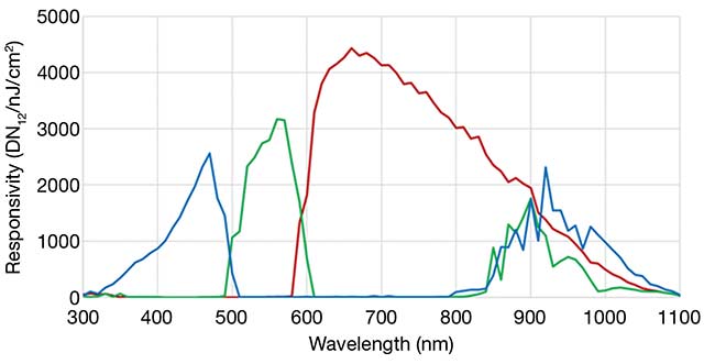
Figure 2. The spectral responsivity of a multifield camera incorporating wafer-level coated dichroic filters. Unlike the bands of dye-based filters, the crosstalk among the red, green, and blue bands of a dichroic filter can be engineered to achieve an averaged optical density (OD) 3 out-of-band rejection. This effectively isolates multiple light sources in the wavelength domain for vision applications. Courtesy of Teledyne DALSA.
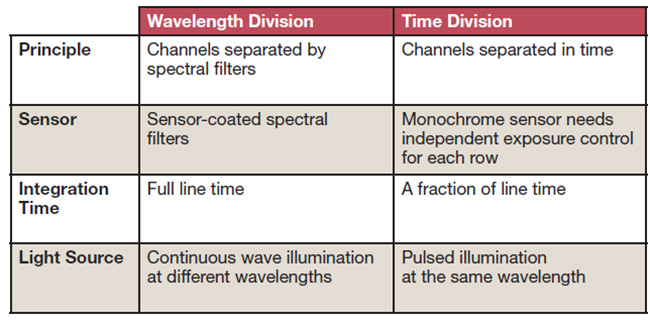
Wavelength vs. time division
There are two approaches to multifield imaging (see table). Wavelength-division techniques use spectral filters to isolate channels by wavelength, while time-division techniques isolate them in the time domain (Figure 3).
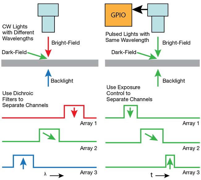
Figure 3. A schematic comparing the two multifield imaging techniques. In the wavelength-division approach, various light sources with different wavelengths illuminate the imaged object using different angles of incidence. Each wavelength is isolated spectrally by filters, and images are captured simultaneously at all wavelengths (a). Time-division multifield imaging matches light pulses with exposure times to separate images in time (b). CW: continuous wave; GPIO: general-purpose input/output. Courtesy of Teledyne DALSA.
Wavelength-division multifield imaging allows for maximum integration time and simpler implementation of continuous-wave light sources. The spectral windows of the dichroic filters used in this technique were designed in consideration of the LED lighting commercially available in today’s marketplace. Now, however, more and more narrowband LED light sources with different wavelengths are available, which makes wavelength-division techniques easier to implement.
Time-division multifield imaging can employ monochrome sensors without any filters. It separates images in the time domain by controlling camera exposure times. For example, Teledyne DALSA’s Linea ML 16K camera has three rows that can independently set when they start and stop the optical integration of each row, without any overlap. The advantage of such time-division approaches is that they are not subject to spectral crosstalk and can be enhanced with pulsed LEDs that emit high-intensity illumination. However, this approach cannot use the full line time for integration and requires more complicated and expensive designs to accommodate pulsed lighting.
Filters and light sources
The key enabling technology for wavelength-division multifield imaging is dichroic filters. The difference between these and traditional dye-based color filters is the level of spectral crosstalk each permits.
Multifield dichroic filters are thin-film-based interference filters engineered to have minimum spectral crosstalk, while conventional dye-based color filters use absorptive organic dyes with significant spectral overlaps between channels. On average, silicon wafers with dichroic filter coatings have been demonstrated to achieve sufficient optical density to provide enough out-of-band rejection for most vision applications.
In current multifield cameras that employ time delay integration, the sensor consists of three TDI arrays with 128, 64, and 64 stages, respectively, that are coated with dichroic filters at the wafer level. The pixel array with 128 stages is the blue channel and is double that of the others to compensate for the sensor’s lower quantum efficiency in the shorter wavelength region. Overall, current camera sensors implement three spectral windows: red, between 620 and ~800 nm; green, between 520 and ~570 nm; and blue, between 420 and 470 nm. These spectral windows can each be engineered to have different wavelength ranges or different spectral line shapes.
The LED light sources chosen for a multifield imaging application need to fit into the spectral windows of the camera’s filters to minimize spectral crosstalk. If the bandwidth of the light source is wider than the filter window, then an additional external narrowband filter might be needed in front of the light source. The advantage of dichroic filters is that, unlike dye-based filters, they can be tailored to specific windows according to application requirements. With commercially available LED light sources, <0.5% spectral crosstalk between the channels can be achieved.
For certain applications using strong laser excitation, a higher degree of channel isolation between the excitation and the image might be necessary. An additional external notch filter can be used in front of the camera in such cases. This will filter out any wavelengths from the excitation source from entering the imager.
Multifield imaging at high speeds
Automatic optical inspection (AOI) is an important process in modern manufacturing operations, such as production of flat panel displays, printed circuit boards, and lithium-ion batteries. In the displays for cellphones, monitors, and televisions,
millions of thin-film transistors are
patterned on a piece of glass in multiple processing steps in a fab. At the end of each step, the glass needs to be inspected to identify possible shorts, opens, contaminants, scratches, and other defects before it moves to the next step. As the pixel density of these displays increases, defect sizes are getting smaller. Many AOI
systems today are designed to inspect
defects smaller than one micron. Therefore, ensuring high system throughput becomes crucial for inline inspection machines to meet the tact time requirements of the production line.
At the same time, the shrinking size
of defects is also challenging their detectability (Figure 4).
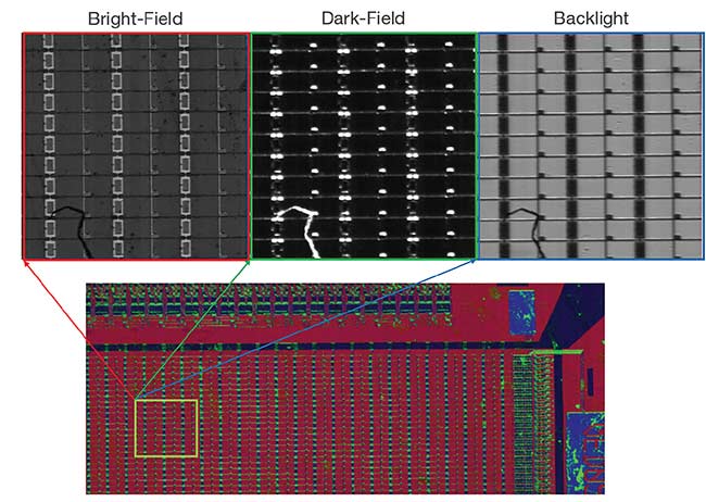
Figure 4. Multifield camera images of thin-film transistor patterns etched into the glass layer of an electronic display. The bright-field, dark-field, and backlight images were captured simultaneously by the multifield camera, but all reveal different data. Courtesy of Envision.
Employing different lighting configurations can optimize the image contrast for different types of structures and defects in these displays. For example, dark-field imaging is best for identifying surface scratches, while backlight imaging is
effective for revealing geometric defects.
In most cases, the bottleneck of an AOI system involves the mechanical movements required during the scanning process. By eliminating the need for multiple scans, multifield imaging can significantly improve the throughput compared to traditional AOI system designs. It also allows much better alignment of multiple images because all of the image data is captured simultaneously in the same
mechanical movement. In this case,
random vibrations would also have a minimal impact on the alignment accuracy of the images.
In addition to supporting applications that require different lighting angles, multifield cameras can also be used for conventional color imaging based on white-light illumination. In these scenarios, the unique spectral characteristics of dichroic filters offer a very different color image compared with dye-based filters. For example, the RGB components of common colors in printed circuitry boards — such as yellow, gold, and green — appear to have much more separation
in the color space. This results in a 53% improvement in the detectability of these common colors in electronic circuit boards (Figure 5).
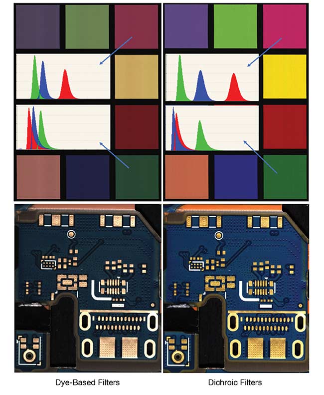
Figure 5. Comparative images of a printed circuit board captured using dye-based filters (top left) versus using dichroic multifield filters (top right). The yellow-gold and green colors appear to have much more separation in the color space using the dichroic filters. Because copper and gold are common materials in electronics circuitries, the multifield camera proves to be a very effective tool in detecting defects related to copper and gold materials in electronics assemblies (bottom). Courtesy of Envision.
Dichroic filters can have similar spectral characteristics to an optical prism, which enables better color separation due to minimal spectral crosstalk. In the early days of color cameras, prisms were commonly used to separate color channels. But prism-based cameras have a comparatively large footprint and need special lenses because the optical system deviates from the thin-optics principle. This further leads to poor reliability and higher system costs. Dye-based color filters offered a simple, robust, and lower-cost solution. But new dichroic filter technology can offer the unique spectral characteristics of prism-based cameras in smaller form factors.
Future trends
As vision technology continues to evolve, it is expected that CMOS sensors will increasingly be combined with advanced filters. In the past few years, for example, the development of RGB-NIR multispectral imagers has helped to introduce new vision capabilities3.
For print inspection applications, adding the NIR channel to a visible-range
imager can help to detect invisible security inks printed on bank notes, passports, and other documents. For the inspection of electronic printed circuit boards, infrared image data permits a deeper penetration depth to reveal defects underneath the surface. In food sorting applications, multispectral RGB-NIR imaging helps to identify a broader range of foreign materials. Consequently, multispectral imaging has been increasingly adopted for such applications. Many industries are upgrading from traditional color imaging to multispectral imaging.
Comparison of Multifield Imaging Technologies
Dichroic filters enhance these capabilities because they can be designed to fit any spectral bands as required for a
specific application. Spectral line shapes can also be tailored by engineering
multilayer thin-film structures. This capability could help to develop specific cameras that are able to image fluorescence from various biomarkers in the
life sciences in a single scan, for example. Combining time delay integration and dichroic filter technologies is expected
to provide further breakthrough solutions to meet today’s demanding requirements.
Meet the authors
Xing-Fei He, Ph.D., is senior product manager at Teledyne DALSA in Waterloo, Canada.
He holds B.Sc. and M.Sc. degrees in semiconductor devices from Zhongshan University and a doctorate in laser physics from The Australian National University; [email protected].
Sungho Huh is vice president of product management at Envision Co. Ltd. in Seoul, South Korea. He holds a master’s degree in electronic engineering from Kyungpook
National University; [email protected].
References
1. X.-F. He and N. O (2012). Time delay integration speeds up imaging. Photonics Spectra, Vol. 46, No. 5, pp. 50-54.
2. X.-F. He (2013). Trilinear cameras offer
high-speed color imaging solutions.
Photonics Spectra, No. 5, pp. 34-38.
3. X.-F. He (2015). Multispectral imaging
extends vision technology capability.
Photonics Spectra, Vol. 49, No. 2,
pp. 41-44.
/Buyers_Guide/Teledyne_DALSA_Machine_Vision_OEM_Components/c3374
/Buyers_Guide/Envision_Co_Ltd/c20510