Systems integrators are leveraging novel lighting methods to simplify spectral imaging.
JEREMY BRODERSEN, SMART VISION LIGHTS
During the past few years, color and spectral imaging approaches have become more prevalent in machine vision system design. Today, machine vision lighting companies and industrial camera designers are working to provide multispectral solutions for industrial applications by either adding more color channels to their standard red, green, blue (RGB) cameras or by implementing new lighting methods for performing spectral analysis. With reduced hardware and computing costs, and advancements in vision software, these tools have become viable options for integrators over a wide range of applications. The following is an overview of two methods of spectral imaging: one involving fully integrated multi- or hyperspectral camera systems, the other offering a simplified approach that utilizes multispectral lighting with grayscale imaging.
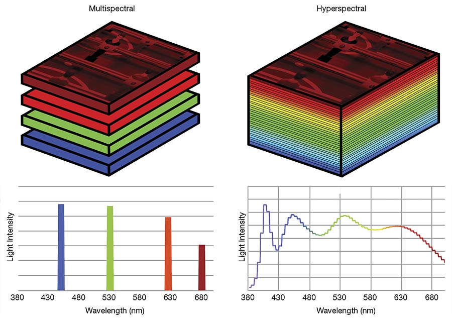
Figure 1. The multispectral image cube contains four images to produce a coarse distribution (left). A hyperspectral image cube contains many more images to produce smooth spectral data (right). Courtesy of Smart Vision Lights.
In spectral imaging, an object’s
spectral information is parsed into
multiple images, with each image resulting from a different wavelength band reflected or emitted from the object. The wavelength range of images
can span from the ultraviolet to near-infrared (NIR) using standard silicon-based sensors, and into the NIR/shortwave infrared (SWIR) region using InGaAs and other SWIR-compatible sensors. Images from each wavelength band are combined into a data matrix called an image cube. An image cube is essentially a stack of images in which each image in the stack corresponds
to a discrete spectral band. The number of spectral bands in the cube differentiates hyperspectral from multi-
spectral imaging. “Hyper” implies the accumulation of tens to hundreds of wavelength band images, and “multi” consists of more than one spectral band image (Figure 1).
With the fine spectral resolution of hyperspectral imaging, a nearly continuous spectrum can be resolved at each pixel location, allowing for chemical and elemental analysis. Multispectral imaging is a coarse application of spectral imaging in which the variation in spectral content does not require the fine resolution that hyperspectral provides.
Capturing multiple spectral bands
Multispectral imaging generally refers to an imaging system capable of capturing more than one spectral band. A simple example is color imaging. Color images are constructed from three spectral band images corresponding to blue, green, and red color channels. By analyzing image cubes with more specific spectral resolution or range — for example, spectral bands ranging from UV to NIR — machine vision systems can resolve important object or material features that are beyond the capabilities of traditional machine vision solutions. Today, companies are using multispectral imaging for applications such as inspecting fruits and vegetables, recycling materials, and sorting pharmaceutical products, as well as for applications involving the processing of animal-based products.
Generating a spectral image cube requires a means to separate the light reflected from the object into a multitude of individual spectral band images. With spectral camera systems, wavelength band selection is achieved by one of several methods involving light diffraction, light refraction, and interference filtering. In some camera systems, including standard RGB color sensors, interference filters are applied directly on the sensor pixels using thin-film techniques, while other spectral cameras separate light using a filtering subsystem placed in front of the camera sensor. Typically, spectral camera configurations are accompanied by broad spectrum light sources that cover the camera’s spectral range.
An alternative multispectral vision system flips the traditional design on its head. Simplified multispectral imaging uses the light source for spectral selection and a standard grayscale camera to capture the spectrally filtered image. Instead of separating the spectral content at the camera, discrete wavelength bands are generated sequentially by the lighting system, and subsequent images are collected using standard grayscale imaging.
For example, to construct a color image, a grayscale camera is used along with a light source that contains independently controlled RGB lighting channels. As the light source cycles through each individual color channel, a subsequent image is captured. Each of the three images corresponds to the object’s reflectance for red, green, or blue. From this, a full-color image can be constructed by combining the three images into one RGB image. Similarly, certain features can be isolated from the rest of the image based on how they respond to the various lighting
colors. This approach has several benefits. Unlike with standard color imaging, the resulting image resolution matches the full pixel resolution of the grayscale camera. With standard color camera imaging, multiple neighboring pixels are combined to resolve color, thus resulting in a comparatively lower-resolution image. Mechanical filter mechanisms are also eliminated. Together, the result is high-resolution multispectral imaging at lower cost and with less system complexity.
Multispectral lighting provides a simplified approach to multispectral camera imaging and often can provide a practical solution for difficult industrial imaging applications. Although multispectral lighting cannot cover all
spectra imaging application requirements, many applications require only a small set of wavelength bands to generate adequate spectral contrast. In these cases, an assortment of LED source wavelengths can be chosen for each specific application. The advantage of using multispectral lighting to reduce the number of wavelength bands is a reduction in the overall system cost and complexity because standard grayscale imaging sensors and imaging methods can be used (Figures 2 and 3).
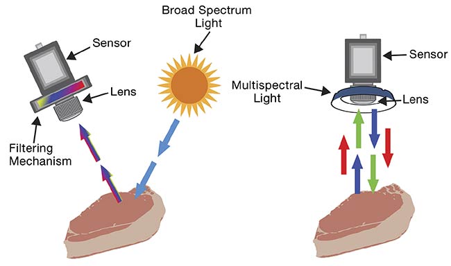
Figure 2. A system that uses a broad spectrum light source and
a spectral camera system (left).
A system that uses a monochrome camera and a multispectral lighting system to cycle through the various wavelength bands (right). Courtesy of Smart Vision Lights.
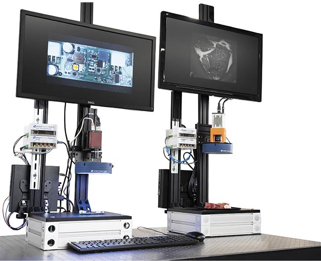
Figure 3. Two multispectral lighting application demo units using grayscale cameras. A multispectral UV fluorescence and color system setup for imaging a printed circuit board that has a fluorescent coating (left). A multispectral shortwave IR (SWIR) system using an InGaAs camera and a multispectral SWIR light setup to image a pork chop (right). Both systems use a grayscale imaging arrangement along with controllers to cycle the camera and LED wavelength-band channels. The colored image on the left monitor is a composite of four spectral channels. Courtesy of Smart Vision Lights.
Food, electronics analyses
One area in which spectral imaging
is gaining traction is food analysis. With the ability to discriminate spectral information along with spatial features, integrators can access object features that cannot be revealed by standard techniques alone. A good example is the analysis of meat. Age, grade, damage, disease, and bone location are characteristic features that researchers and integrators have resolved using spectral imaging. Electronics inspection is another application in which fluorescence, color, and even NIR imaging can be combined and used to reveal complex feature sets such as component placement, trace inspection through solder mask, and board layers, along with conformal coatings and adhesives. The following examples show features that can be revealed and isolated using multispectral lighting.
In Figure 4, a multispectral lighting arrangement using SWIR LED wavelengths and a grayscale InGaAs camera is used to resolve various features from a raw pork chop. In the image cube, the fat, muscle, and bone reflect light differently, depending on the wavelength band. Basic arithmetic is performed on the image cube to produce images in which either the bone or the various types of fat tissues are accentuated in high contrast to the other parts (Figure 5).
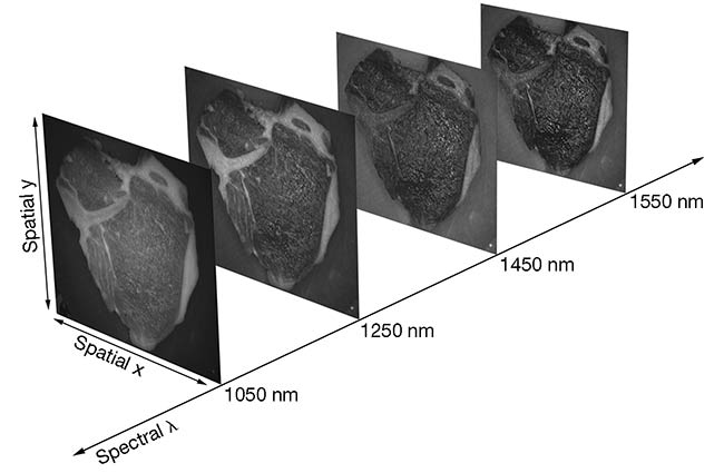
Figure 4. A multispectral image cube of a
pork chop illuminated with various shortwave
IR LED wavelength bands. Courtesy of Smart Vision Lights.
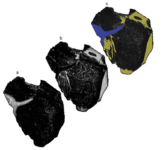
Figure 5. Images that have been processed to accentuate contrast of fat, bone, and meat. To show the bone, the 1550-nm image is
subtracted from the 1250-nm image (a). To show fat, (a) is subtracted from the 1250-nm image (b). A color composite of (a) and (b) (c). Courtesy of Smart Vision Lights.
The setup includes a four-channel multispectral ringlight outfitted with SWIR LEDs that are controlled by a Smart Vision Lights (SVL) LED light manager (LLM) lighting sequencer and a 4ZMD driver. The SWIR camera
system is a Hamamatsu InGaAs C14041-10U.
To evaluate printed circuit boards (PCBs), UV fluorescence is combined with visible lighting to produce a composite image that reveals fluorescence intensity overlayed with color. In Figure 6, a multispectral lighting setup involves using a clear UV-sensitive coating on a PCB component to demonstrate how fluorescence can be combined with color imaging. Note that the fluorescence image is completely separated from the color channels. This separation is possible because the fluorescence excitation channel (a 365-nm LED) is separated from the composite color image channels. The 365-nm UV excitation is filtered out using a longpass interference filter.
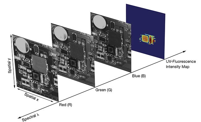
Figure 6. An image cube with four images
is captured using a multispectral ringlight with
RGB and 365-nm wavelength band channels. Courtesy of Smart Vision Lights.
This multispectral lighting system uses four color channels: 365 nm, blue, green, and red. Although not necessarily representative of a real-world PCB application, it shows how a fourth UV-excitation lighting channel can be combined with RGB color channels (or other LED wavelengths) to reveal fluorescence that is independent of the other channel. In the resultant image, the fluorescence information is overlaid onto the composite RGB image (Figure 7a). To show the layer thickness and coverage area, a jet color map look-up table was used to indicate relative fluorescence intensity (Figure 7b).
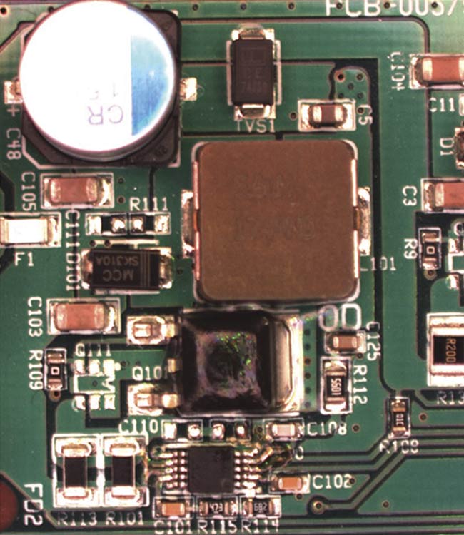
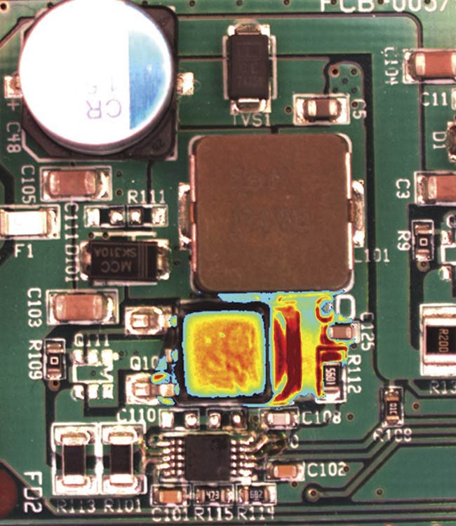
Figures 7. A composite of the RGB color channels from the spectral image cube shown in Figure 6 (top). An overlay of the fluorescence intensity map on the composite color image (bottom). Courtesy of Smart Vision Lights.
The multispectral UV fluorescence and color setup involved an SVL four-channel multispectral ringlight with 365-nm, red, green, and blue LEDs controlled by an SVL LLM lighting sequencer and a 4ZMD driver. Other elements of the configuration included an Allied Vision Manta G-095B camera and a Chroma AT 450lp longpass filter.
As multispectral imaging technology
becomes more prevalent, machine vision systems designers will have a powerful toolset for installing machine vision technology in nontraditional environments, including in farming applications and autonomous vehicles, where SWIR multispectral imaging, UV-VIS, and UV-VIS-IR can be combined into a single camera or lighting arrangement.
Meet the author
Jeremy Brodersen is an optical engineer at Smart Vision Lights.