Near-field scanning optical microscopy (NSOM) is an optical microscopy technique capable of imaging objects with a resolution below the diffraction limit of conventional (far-field) microscopy; i.e., below approximately half the wavelength of the light used.
M. Kovar, Midako A. Nohe, N.O. Petersen and P.R. Norton, University of Western Ontario
NSOM is suitable for studies on the mesoscopic scale (several tens to hundreds of molecular dimensions). It has become an important tool in research and applications of semiconductors, organic layers and membranes, biological materials and optics.
The technique exists under two different names: NSOM results from the focus of the Cornell group on near-field optics, while the name scanning near-field optical microscopy (SNOM), used by the IBM group, stresses its focus on the scanning part of the instrument because of IBM’s previous invention of the scanning tunneling microscope (STM). Thus, the choice of NSOM or SNOM depends on the user’s point of view. This article will use NSOM because of the focus on photonics and the authors’ personal preference.
Far- and near-field light
Far-field light can be described as a propagating wave which spreads out indefinitely if it is not absorbed, refracted or scattered by the environment in which it travels. On the other hand, the propagation associated with near-field light is limited to very short distances from its source. It is often called an evanescent wave to express its confined character. It plays a central role in near-field optics. Thus, the major difference between the far field and near field is the distance of propagation of the electromagnetic wave.
In reality, near-field light is always accompanied by a propagating field because of the way the near-field light was formed and/or because of the scattering of the evanescent wave by surrounding objects — such as a metal film in the case of a tapered optical fiber tip. The distance of propagation of the near-field photon is proportional to the physical dimensions of its source; therefore, sample objects under study have to be in the near-field range to be observable.
The wave character of light causes it to diffract, which limits the spatial resolution of a microscope in conventional (far-field) microscopy. The minimum detectable separation of two objects for a given optical system is called the Rayleigh criterion. The resolution, R, can be expressed as:
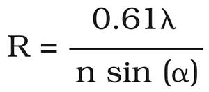
where λ is the wavelength, n is the refractive index of the imaging medium in the object space and α expresses the half of the angle under which the objective sees the object. The typical best achievable resolution of optical microscopy is about 200 to 300 nm.
NSOM can go beyond this diffraction limit because of the highly spatially confined nature of the near-field light. Resolution can be as small as 10 nm.
Principles of near-field optical microscopy
In NSOM, a tapered optical fiber terminated by an aperture with dimensions below the diffraction limit of the light is scanned relative to the sample while the fiber tip is positioned very close to the sample surface (Figure 1). The amplitude of the near-field light decays exponentially as the negative of the first or higher power of the distance from its source. As a rule of thumb, for the near-field effects to be observable, the distance between the fiber tip and the sample surface has to be shorter than the aperture dimension of the optical fiber tip. As a result of the interactions of the sample with near-field light, photons are scattered. Due to the scattering, photons propagate and are detected by a photon detector in the far field. Importantly, just a limited volume is irradiated by the light confined by an aperture. Therefore, the resolution in NSOM is determined by the size of the aperture on the optical fiber tip.
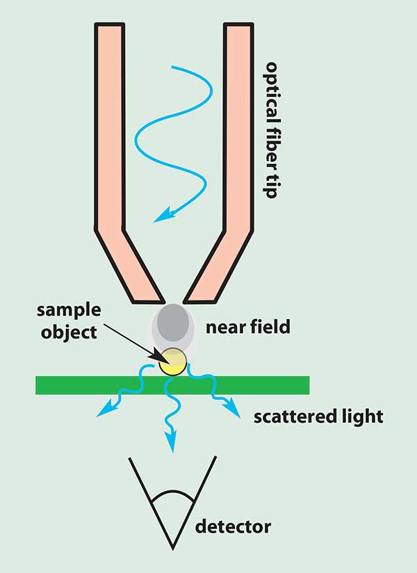
Figure 1. In NSOM, a tapered optical fiber is positioned very close to the sample surface.
The mode in which the near-field light is carried by an optical fiber tip and the sample plays the role of a light scatterer is called the illumination mode (Figure 1).
By contrast, if the sample is irradiated from the bottom (Figure 2) by far-field irradiation, the light is scattered by the sample, resulting in near-field light confined around the surface structures. The illumination angle can be varied from normal to 90° off-normal incidence. In practice, two directions are used the most: normal incidence for the collection mode of NSOM, and the angle at which total internal reflectance occurs in photon scanning tunneling microscopy. The fiber tip then collects scattered photons that are led to the detector through the optical fiber. The resolution is again determined by dimensions of the tip aperture with which the scattered light is collected. This is the collection mode.
Photon scanning tunneling microscopy (PSTM), also called scanning tunneling optical microscopy, is one of the many variants of near-field optical microscopy. The instrument uses photon tunneling into a sharp tip under conditions of total internal reflection. Under these conditions, there exists only an evanescent wave at the surface. The intensity of the evanescent near-field light decays exponentially with increasing distance from the surface. The scanning of the sample can be achieved both in the constant-distance mode and in the constant-height (constant-intensity) mode where photon tunneling is used for tip-sample control.
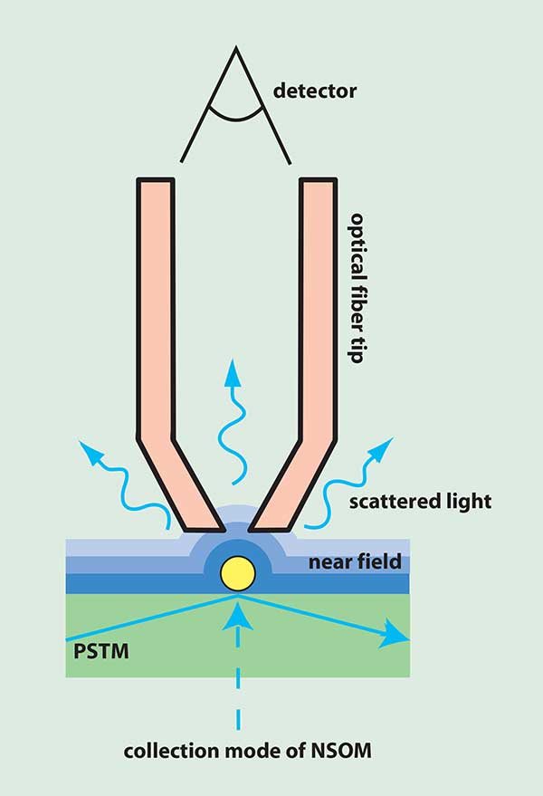
Figure 2. A sample irradiated from the bottom scatters light, resulting in near-field light confined around the surface structures.
In apertureless NSOM, instead of using a small aperture at the end of the optical fiber, a metal tip is used to provide a local excitation. A sharp tip is placed in the focus of a laser beam. The near-field light is formed around the metal tip. The field at the tip is approximately 1000 times stronger than the average field of the laser beam. The instrumental control of the apertured NSOM techniques can also be applied to the apertureless technique as well. The background light is significantly higher than in apertured NSOM and, therefore, signal modulation is very important because it permits detection of only the near-field contribution (modulated signal) while the unmodulated background light is eliminated. Apertureless NSOM might not be suitable for fluorescence measurements where sample photobleaching is an issue because of the intense irradiation of a sample.
The instrumentation for NSOM
A schematic of the illumination mode of NSOM is shown in Figure 3. The technique generally belongs to the scanning probe microscopy (SPM) family. The near-field signal does not participate directly in the feed-back loop required for instrumental control and therefore NSOM instrumentation does not have additional control requirements. From this point of view, NSOM is a combination of a scanning probe with the optics for measuring near-field effects using an optical fiber tip and a photon detector.
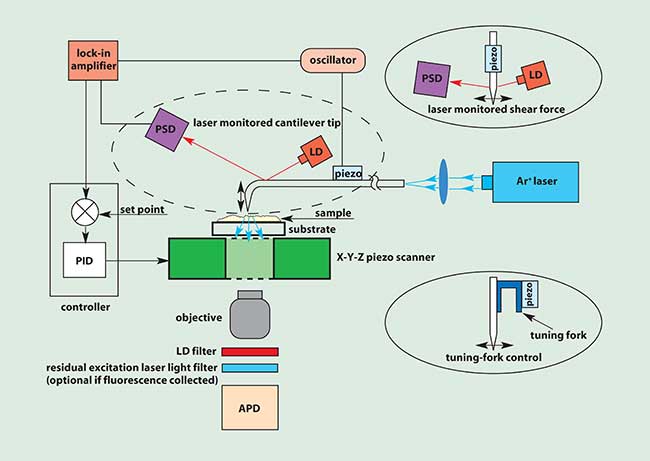
Figure 3. The illumination mode of NSOM generally belongs to the family of scanning probe microscopies.
The scanning of the tip over the sample in the X-Y plane and its control in a Z (vertical) direction is implemented by a piezo-electric scanner. The tip position near the surface is controlled optically. A laser diode (LD) beam is reflected off the fiber cantilever into a position-sensitive detector (PSD). The cantilever position is modulated by vibration with a piezo element attached to the cantilever itself. Using this approach, the near-field light can be separated from the far-field light. The position of a tip is determined by a signal coming from the photodiode quadrants of the PSD. After demodulation by a lock-in amplifier, the PSD signal in the feedback control loop is compared with a set point. The resulting error signal is fed into a controller — currently, the most common type of controller used for SPM control is a proportional-integral-differential (PID) controller. The controller output signal adjusts the tip-sample distance by the Z (vertical) motion of a piezo scanner. In principle, the method is the same as the control in atomic force microscopy. There are two other alternatives often used for the control of the tip: a shear force or a tuning fork; these are shown in two inserts in Figure 3. In shear force control, the optical fiber is straight, and a piezo element creates vibrations parallel to the sample. The amplitude of the shear force is kept constant similarly to the principles used in cantilever tip control. The advantage of the setup lies in the use of a straight fiber which eliminates the loss of light that occurs in a bent fiber.
If tuning-fork control is used, the fiber is straight but its vibrations are tuned to a resonance frequency of the tuning fork. The advantage of the method is that no interfering light coming from the LD is present. Therefore, no filter is necessary in the optical part of the instrument.
In the optical part of NSOM, Ar+ laser light is coupled to an optical fiber by a lens and led to the end of the tip within the fiber. In general, any laser of choice can be used for imaging. The near-field light is scattered by the sample structures, and the scattered light is collected by a microscope objective. An LD filter removes the undesirable light coming from the control LD. Another light filter may be used to remove residual light from the excitation laser in the case of fluorescence being collected. After filtering, photons are detected by an avalanche photodiode (APD).
The illumination and collection modes described above are suitable only for transparent samples. In the case of opaque samples, the illumination of the sample and the signal collection is implemented through the same optical fiber tip. An optical fiber beamsplitter has to be used to redirect the signal to a photon detector.
Fabrication of optical fiber tips
Three basic methods for the fabrication of the NSOM tips can be distinguished: heating-and-pulling, selective chemical etching, and a flat-tip method (Figure 4).
In the heating-and-pulling method (Figure 4a), an optical fiber is locally heated by a laser while its ends are pulled away from each other. As a result of pulling, the tip has a relatively long tapered section where light losses are rather high because optimal conditions for waveguiding are not met. Therefore, the tapered part has to be coated with a reflective metallic layer to keep the light inside the fiber. To prevent it from being coated, the aperture is positioned off the line of sight of the metal source of an evaporator. This method is not expensive, but it can cause unevenly shaped fiber tips. A disadvantage of this approach is that lower laser light power must be used because the long tapered section is heated and the tip can be burned.
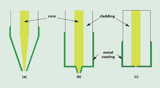
Figure 4. The methods for fabricating NSOM tips include heating-and-pulling (a), selective chemical etching (b), and a flat-tip method (c).
Selectively etched fibers have a shorter tapered section (Figure 4b) which results in much lower losses in the tapered section and therefore much higher transmission. The solution for etching consists of a buffered aqueous solution of HF and ammonium fluoride — standard etchants used in the microfabrication industry. The shape of the tips can be controlled with the etchant ratio, concentration, and time of immersion. If the whole tip is covered by a metallic layer, the aperture is fabricated by focused ion beam (FIB) milling.
An optical fiber does not need any special treatment for the fabrication of flat tips (Figure 4c). The end of the fiber is completely coated by a metallic layer and an aperture is milled in the metal film using FIB milling.
With the growing interest in NSOM, new methods of tip fabrication will emerge which do not use an optical fiber but are microfabricated using the methods of the semiconductor industry.
Imaging and spectroscopy with NSOM
In imaging and spectroscopy with NSOM, light intensity is detected as a result of strong electromagnetic interactions between the probe and the sample structure in the near-field via evanescent photons. The theory behind NSOM imaging and spectroscopy is developing rapidly. Despite progress in many important aspects of near-field optical microscopies, no theory has yet been developed that reliably describes all the complex imaging effects and artifacts observed in various applications.
Since NSOM uses electromagnetic radiation, specific information on a measured system can be gained using different photon energies, polarization or detecting fluorescence where it is appropriate.
Furthermore, imaging can be influenced by probe-sample interactions. In general, NSOM is very sensitive to the distance between the tip and the sample, which can lead to topographical artifacts when the image contrast is due to distance changes instead of optical characteristics of the sample. In addition, the sensitivity of NSOM to the tip-sample distance increases with increasing resolution. However, the sensitivity to tip-sample distance is not so critical if fluorescence is collected. Despite all these difficulties, NSOM can also be used for single molecule microscopy and microscopy of larger single molecules due to its high resolution.