Specifying the right components and understanding the strengths and limitations of available imaging techniques at the outset are key to a project’s success.
DAVID L. DECHOW, LANDING AI
While 3D imaging in machine vision has been applied in key use cases for many years, use of the technology has recently grown and expanded, making it increasingly common in a wider range of applications. The best practices that can help to ensure a successful 3D imaging project involve component specification and project implementation. However, it’s important to start with an overview of 3D imaging and a review of the methodologies available in the marketplace.
A useful way to think about 3D sensing and imaging systems is to understand that in virtually all of these components the 3D information is derived by processing one or more 2D images, often with associated unique and very specific illumination strategies. Put more cleverly, “3D is 2D.” It may seem like a trivial point, but this detail will help to clarify the various available imaging techniques and their strengths and limitations.
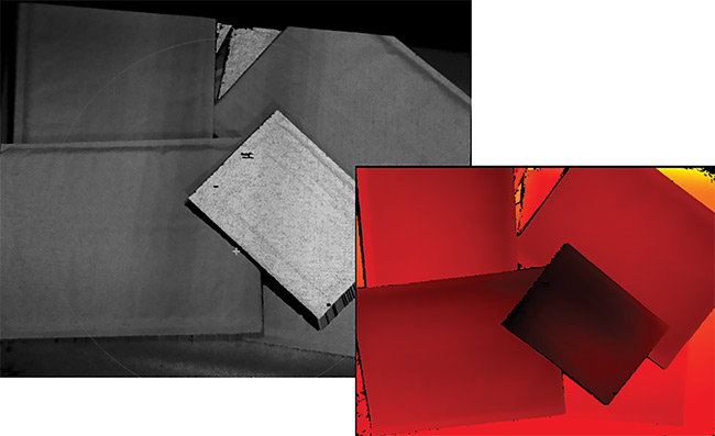
Figure 1. A grayscale contrast (2D) image (left) and its related 3D point cloud (right). Courtesy of David L. Dechow.
A 2D image contains what is referred to as contrast data. Features are defined by the relationship of their color or grayscale compared to that of neighboring pixels. In a spatially calibrated 2D image, these features, and even individual pixels, have a known, world-measurement relationship to the other features in the image. Using this image information, along with further information related to the geometry of the imaging system and illumination, a 3D imaging system can then provide 3D data about a scene.
The data in a 3D image, at its most basic level, is a collection of xyz points called a point cloud. The point cloud can also be referred to as a range or height map, with the z-component of each point relative to a specific plane, depending upon the imaging technique and the imaging components used. With the point cloud data representation, further processing is then required to, for example, extract a single point in the scene (such as the highest point above a plane), isolate features or objects based upon spatial height relative to a plane for measurement or quality evaluation, or search for and provide the location of objects in a complex scene based upon a stored 3D model of the object’s shape, often for the purpose of robotic guidance (Figure 1).
In short, the spatial relationships between individual neighboring 3D points are used to extract information, much like the contrast relationships between neighboring pixels in a 2D image are used to extract features and objects in the image. With the acquisition of a single view of a feature or object, the 3D information represents only the surface of the scene — a single plane as viewed by the imaging system — and not a full 3D representation of all of the surfaces of an object. Creation of data that depicts the 3D view of an entire object requires multiple images of the object, covering all surfaces, and this use case is found mostly in applications for 3D reconstruction, typically as an off-line process.
Keep in mind that the purpose of 3D imaging is to extract objects, features, or defects in a scene by analyzing geometric structure and relationships, as opposed
to 2D imaging, which analyzes contrast relationships. When properly calibrated, 3D imaging provides geometric information that is related to real-world measurements and even to real-world coordinates (as in vision-guided robotics or autonomous vehicle guidance).
The actual implementation of 3D sensing and imaging has been greatly facilitated by readily available components and technologies in the machine vision marketplace that offer self-contained solutions for acquiring 3D data.
Acquiring 3D data
The methods for producing and processing a 3D image vary widely by component, and determining the best-suited technique for a given application is essential when implementing the technology. All 3D images are similar, but the ways that basic images are acquired and processed differ. In most 3D imaging techniques, the acquisition of a suitable 2D image is still a basic requirement, and illumination plays a key role in the result. Some typical 3D imaging approaches, with brief descriptions of their general characteristics, follow.
Passive imaging (single or multicamera). Passive 3D imaging uses standard illumination to acquire the camera’s image, and the approach requires no special lighting techniques. This method generally requires that the 2D scene have well-defined visible features or texture.
Active imaging (single or multicamera). Active 3D imaging uses structured lighting to create visible features on the surface of a scene. This increases the
precision and reliability of the 3D imaging in many cases. Systems with active lighting can take a single image of a
pattern or multiple images of various
patterns, either as an option or as a
requirement of the technique (Figure 2).
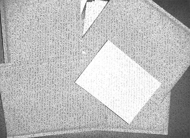
Figure 2. Structured light in active illumination 3D imaging provides texture and 3D reference for more accurate 3D data. Courtesy of David L. Dechow.
Laser triangulation scanning. Also called sheet-of-light scanning, this technique creates a 3D image using a laser (or other type of structured) line of light that is imaged by a camera at a set or calibrated angle to the line. The calibrated system calculates the height of points by the position of the line in the field of view and combines many line images into a full 3D representation of the object by either moving the light line, the object, or the camera itself. (In measurement applications, these devices might also be called profilometers.)
Time of flight, lidar, and ladar. Time-of-
flight (TOF) imaging does not explicitly start with 2D data, but rather uses specialized imaging sensors and/or camera processing to calculate a distance for each pixel by timing pulsed or phase-modulated light reflections. Lidar (light detection and ranging) and ladar (laser detection and ranging) are terms defining imaging technologies that relate to TOF, but these approaches typically use a scanning technique to evaluate distance. A technology called flash lidar, however, does not scan but uses a wide beam laser illumination source such as a TOF camera.
Other imaging methods — such as depth from focus, photometric (shape from shading), and light-field imaging — are also available for applications in industrial automation.
The successful implementation of any of these technologies can be affected by several fundamental best practices, a few of which follow.
Understanding the limitations of 3D
Limitations, some of which are obvious and others that are not so obvious, can affect the success of 3D imaging in industrial applications. As with virtually all imaging technologies, interference from ambient light can cause problems in 3D applications. Even when using systems that employ internal or active illumination, excessive ambient light will affect the quality of the 3D point cloud when this light obscures the 3D lighting. Also, as in 2D imaging, in areas where glare exists — either due to the object reflectivity or ambient light — data will be absent. Compounding this problem is the architecture of many typical 3D imaging use cases involving plant floor implementation, where physically blocking ambient light may not be practical. Users of 3D imaging systems should be sure to identify potentially problematic ambient light situations in advance, and, where possible, use bandpass filtering to optimize any monochromatic illumination that may be used by the 3D system. Also, users experiencing these conditions might consider specifying a 3D imaging component that implements software or imaging techniques to indicate the ability to reduce glare in the image.
Almost all 3D imaging techniques exhibit dropout of 3D information due to the geometry of certain objects being imaged. This dropout occurs when the angle of the illumination relative to the camera angle causes some of the part geometry to be hidden from the light or the camera. A fundamental best practice is to ensure that the object surface of interest is aligned with the camera and illumination angles in the 3D system. In some cases, though, this may not be possible due to part variation and variations in their positions, particularly when dealing with randomly oriented parts. Some 3D systems incorporate opposing or even multiple cameras, a feature that can be very useful, to help overcome dropout. However, these additional cameras can add algorithmic complexity, cost, and processing time to the solution (Figure 3).
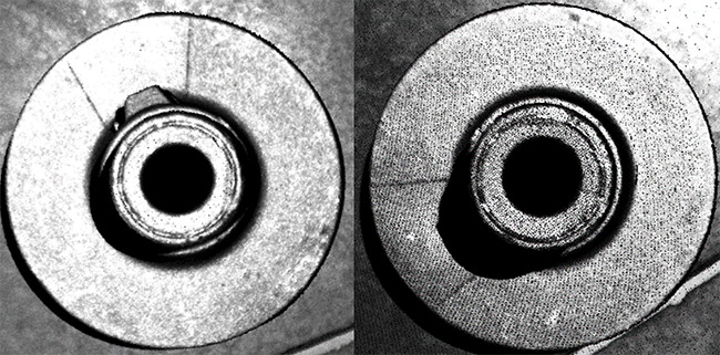
Figure 3. An example of 3D dropout due to occlusion. The parts are identical, but the point cloud on the right does not show the feature on the hub because the 3D data could not be produced due to shadowing. Courtesy of David L. Dechow.
Evaluating resolution and performance
In 3D, the resolution of the imaging is determined by both illumination and acquisition technique, and it is also affected by the image resolution of the sensor(s) used in the system. The important image resolution of a 3D system, however, is not necessarily the resolution of the sensor, but, rather, the density of the point cloud delivered by the system. In certain
systems this density is not a 1:1 relationship to the number of pixels in the sensor.
Ultimately, the number of points in the point cloud may be of principal interest
for some applications, such as defect detection, assembly verification, object recognition, and others. However, another metric for 3D imaging performance is the measurement accuracy (or precision) of the system when identifying the position
of features within the image. This performance might be stated in terms such as
z-accuracy or xy spatial resolution.
Because no standards or common terminology exist for stating 3D imaging system performance, it is a good practice to clarify published metrics relative to
each application, and/or to test the system
to empirically determine practical capability.
Specifying the right technology
The most important step for 3D imaging — and a constant for all automated imaging applications — is to perform an initial, thorough evaluation of the requirements of the target application. This should be done without consideration of the specific technologies that might be used, as it is all too common to see 3D imaging specified for an application, where a more critical analysis of the task would have shown that using a less complex method could be equally successful.
Take, for example, a surface inspection where small, localized defects (for example, chips or pits) might exist above or below the surface. While 3D imaging can identify and measure these defects to some level of resolution, the question becomes whether it is necessary to accurately quantify the defect geometrically, or whether it is enough just to detect a condition where the surface is not smooth. For discrete height/depth measurement, perhaps 3D imaging is indicated. In the case of the latter, more subjective, specification, however, 2D imaging with creative illumination could perform very reliably if the illumination and imaging were used to highlight the geometric surface features (Figure 4).
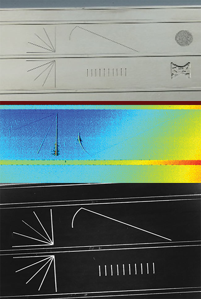
Figure 4. Extracting the surface features of a part (top) may be possible using 3D imaging (middle). However, prudent application of illumination highlights the features in a 2D image (bottom). Courtesy of David L. Dechow.
In the specification of 3D components for specific applications, consider the strengths of each component and the way each one will be used in the imaging task. The following discussion focuses on several 3D technologies, specific applications served by them, and key best practices.
Vision-guided robotics
One of the more high-profile applications served by 3D imaging technologies is robotic guidance, or vision-guided robotics (VGR). While 2D positional information is suitable for many VGR tasks, 3D location offers the ability to locate an object in any orientation and spatial position. This kind of flexibility provides greater opportunities for VGR in a growing base of applications. Objects that are not resting in a specific plane can be reliably located for picking or processing, potentially even when they are randomly stacked or piled. A broad range of automation applications in areas such as assembly, packaging, and machine tending can achieve greater flexibility by using 3D guidance. And most industries — including automotive, metal fabrication, logistics, and distribution — can profit from the use of this VGR technology.
3D imaging technologies that are most suited to VGR applications include active imaging components and scanning sheet-of-light components. A typical VGR application requires medium to high
accuracy in determining a pick position, but a best practice may be to include a regrip, or a reinspect of the object once it is in grip, to overcome variations that could occur in the gripping process. (In VGR applications, a more important consideration may be the accuracy required when placing the part.) Other components, such as static sheet-of-light profilometers or TOF imagers, may be considered, but these devices have limitations for this application. A profilometer requires movement of either the device or the part, which may not be practical, and TOF
images typically provide too little accuracy for most VGR applications.
Other 3D applications
Alternatively, sheet-of-light or laser line profilometry is well suited for 3D surface feature measurement and defect detection, with some important considerations. While these techniques may produce higher fundamental accuracy than other typical 3D imaging methods used in an automation environment, the requirement that either the part or imager must scan or move to acquire an image can introduce error that adds to the raw fundamental accuracy of the imaging method. Because many individual images are stitched together to form a full 3D representation, variations within the images — sometimes caused by part or component vibration — introduce measurement error and even obscure defects. A practical rule of thumb is to ensure that vibration is kept to a minimum and to include the amount of vibration in the calculation of potential system measurement accuracy.
3D imaging is increasingly being used
in logistics and warehousing. Both structured light imaging systems and TOF cameras are well suited to performing tasks such as on-line volumetric calculations of objects and/or boxes moving on a conveyor belt. The key to this inspection is the ability of the imaging system to capture single-shot 3D images to over-
come the motion blur that would be
significant in systems that require
multiple snapshots. The TOF camera is well indicated for this application, but users should be aware of its limitations in accuracy and measurement resolution.
With the overall maturity of the available 3D imaging systems, the use of 3D
in machine vision applications is expected to continue to expand. Implementation
has become easier. And, by paying
attention to best practices, users can be confident in the success of the technology in a variety of automation tasks.
Meet the author
David L. Dechow is vice president of outreach and vision technology at Landing AI, where
he works with cross-functional teams to
support LandingLens, the company’s unique deep learning-based automated inspection product. He is an experienced engineer,
programmer, and entrepreneur specializing in the integration of machine vision, robotics,
and other automation technologies, and he
has an extensive career in the industry; email: [email protected].