Evolving sensor technologies are providing more and better data from laser materials processing operations to better monitor welds and identify flaws, and to automatically optimize the welding process.
ANDREAS THOSS, CONTRIBUTING EDITOR
Welding is an ancient technology. Five thousand years
ago, Egyptians used it to join copper water pipes together. Over the centuries it evolved into an essential technology to fuse various types of metals as experienced welders learned to optimize the process by observing and reacting to colors in the material and the flames. Welding technology has made more progress in the last 50 years than it did in the preceding millennia. A crucial part of this development relies on optical sensing of process parameters far beyond what our eyes can perceive.
The monitoring of such parameters has become a technical task in which photodetectors and cameras record radiation during the welding process. Spectroscopic measurements deliver the exact temperature with good temporal or geometric resolution. And x-ray and ultrasonic methods enable post-process evaluation of features deep inside the bulk material.
The laser beam, meanwhile, has propelled advancements in welding technology faster and farther in recent decades. The beam not only transports large amounts of energy with extreme precision to the joining partners but also enables
illumination and observation of the welding process. Some modern optical technol-
ogies even look inside the melt pool.
Closing the loop
Process development in welding has always been a lengthy business of trial and error involving many post-process analyses of weld samples. In recent years, optical technologies have evolved that have helped to speed these developments by evaluating weld quality in much shorter time frames. Such capabilities raise the questions of when and where this data can close the loop to make welding an automated process in a self-controlling production environment.
“Actually, we are pretty much there,” said Peter Abels of the Fraunhofer Institute for Laser Technology ILT in Aachen, Germany. In May, Abels chaired the Process Control & Digitization forum at the AKL’22 International Laser Technology Congress, where experts from industry and academia met to discuss progress toward welding with inline process control.
“Today we have a large variety of sensors to monitor the joining process before, during, and after the actual laser welding,” he said. “They deliver a lot of very detailed data. The challenge is to understand the data, preferably in a short time.”
The goal of welding is to join two parts. The quality of the weld seam is most often tested through post-process analysis such as x-ray or computed tomography. In addition to such nondestructive testing methods, parts can be cut and etched to evaluate the process performance. Obviously, only fast nondestructive testing techniques can be helpful for closed-loop process control. Several approaches are in development, Abels said.
Seeing the unseen
Looking inside the weld pool would have seemed unthinkable a few decades ago. For Markus Kogel-Hollacher, coordinator of R&D projects at Precitec GmbH & Co. KG, it is a daily business.
The German manufacturer of process monitoring equipment has been working for several years to develop a method that uses optical coherence tomography (OCT) to measure keyhole depth during welding processes. Precitec’s technology sends a broadband laser signal along the path of the welding laser. Part of this signal is reflected on the end of the welding pool and compared with a reference signal inside the laser head. The interference of the two signals provides the keyhole depth. The technology cannot look through metal, but the OCT signal passes the vapor inside the weld pool (Figure 1).
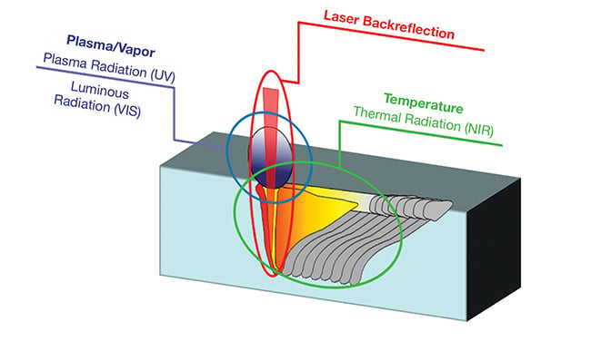
Figure 1. The fundamentals of laser welding monitoring. A number of physical parameters are accessible for measurement during the welding process. To support inline process control, they must be directly associated with process results such as welding depth or the occurrence of pores or spatters. Courtesy of Precitec.
OCT was originally developed to map the interior of the human eye. Applied to the welding process, the imaging technique can measure keyhole depth with micron precision and improve throughput through automation and reduction of post-process testing.
One of Precitec’s customers applied OCT process control to its manufacture of automotive seat recliners. “The main reason for the introduction of the sensor was the reduction of post-process nondestructive testing, which resulted in a payback of the system in a very short time,” Kogel-Hollacher said. In this production system, he said, the standard deviation of weld depth was reduced by 40% to 50% due to active control of the welding laser by OCT data.
For another customer, Precitec used OCT to measure the layer thickness in a directed energy deposition additive manufacturing process. In this process, metallic powder is blown onto a surface and melted with a laser beam. Engineers determined from the sensor data that the powder feed rate had the greatest impact on layer thickness. Thanks to the closed loop enabled by the OCT sensor, the collected data could be fed into a Siemens control system to allow adaptable building strategies, Kogel-Hollacher said (Figure 2).
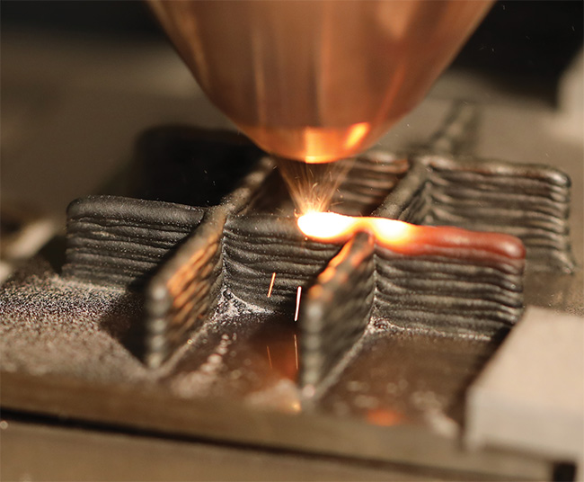
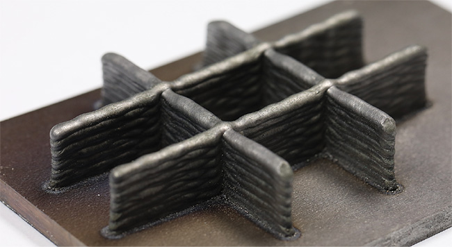
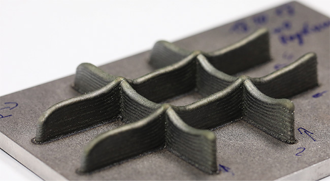
Figure 2. The laser material deposition process (top). Without OCT-enabled process control, all layers will be the same height (middle). With OCT-enabled controls, the deposition system can vary the thickness of each layer to create special shapes (bottom).
Courtesy of Precitec/Siemens.
Using AI for OK/NOK decisions
Michael Ungers, product owner at Scansonic MI GmbH, uses a well-established camera-based sensor technology in combination with artificial intelligence (AI) to automate quality control in laser materials processing. First results were achieved in laser brazing.
“We have a camera that looks on the laser process and records images from the area before, during, and after the actual laser process,” Ungers said. “And we trained a neural network to identify problems such as pores or spatter in these images.”
Scansonic has produced optics for industrial brazing and welding since 2000, including its ALO4 laser head (Figure 3). The device is equipped with a process monitoring system that captures images of brazing processes and feeds them into a neural network capable of classifying pores and spatters.

Figure 3. Scansonic’s ALO4 industrial laser head for laser brazing and welding is equipped with an integrated process monitoring system that features illumination, recording, and control elements. A cover glass on the bottom side protects the lens against contamination from the industrial environment. One additional task of the system is to automatically monitor the condition of the glass. Courtesy of Scansonic MI GmbH.
Pores and spatters are two critical measures of the quality of the brazing process. Their sizes and numbers are used to classify OK versus NOK (not OK) parts. From the process images and classification data, the system learned to classify seam imperfections. After the initial training, the AI’s neural network was applied to other samples, and the results were verified. The training ended when validation errors were minimized (Figure 4).
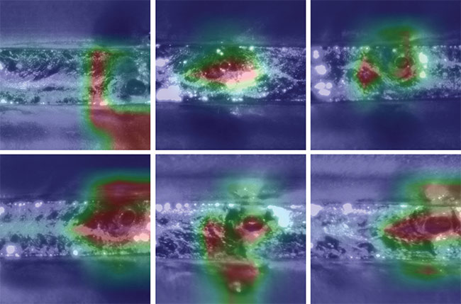
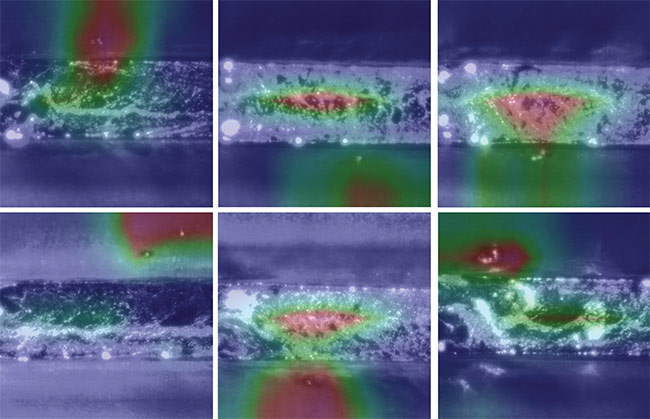
Figure 4. Regions of interest were mapped on test samples by an AI system trained to detect the presence of pores and spatters — two
critical measures of the quality of industrial brazing processes. The system identifies images that contain pores or spatters, without identifying the pores or spatters themselves. Three columns of images show pores (top), and three show spatters (bottom). Courtesy of Scansonic MI.
“We trained the system for a customer who uses laser brazing for the roof seam of cars. The AI ended up with a failure detection accuracy of up to 98%,” Ungers said.
In operation, the AI identifies images with pores or spatters and then marks the part as OK or NOK. The system works in near real time, enabling quality evaluation during the normal production cycle, a critical requirement for inline quality monitoring.
Currently, the system does not analyze process parameters, but the quality data can also be used for process control.
“That is still a future option,” Ungers said. “By combining process data and image data, AI will be a powerful tool to not only check the quality but to further understand which parameters need to be adapted to end up with a high and constant production quality.”
Listen to the process
Another less strictly visual approach to process monitoring uses photodetectors to considerably extend another human sense: hearing.
An experienced welder can listen to the welding process for indications of problems. But human hearing is limited to about 10 to 15 kHz. Balthasar Fischer, a physicist and sound engineer, invented an optical microphone that detects sounds up to several megahertz in range, and thereby detects changes in the welding process, like sophisticated optical sensors can.
The sounds of interest originate from the weld pool. During the welding process, dramatic changes in the material’s temperature occur: Material is evaporated and ejected; cracks form. The weld process becomes a source of broadband ultrasound that is transmitted in air. A person can hear a small fraction of this sound when listening to a welding process with the ear alone.
Fischer’s microphones can record acoustic signals from 10 Hz to as high as 2 MHz. The technology is not based on the piezo effect but rather measures the minute changes in air density that a sound wave creates within the cavity of a tiny Fabry-Pérot interferometer. Such interferometers consist of two semi-reflective mirrors, between which a lightwave travels back and forth. As the optical path length of this wave changes with sound-induced air density variation, so does its interference signal — a principle that is not frequency dependent. The interference signal is measured and digitized with 24-bit resolution at 2 MHz. A short-time Fourier transform delivers up to about 32,000 acoustic spectra per second. The probe is small and easily integrated near the process zone.
The company XARION Laser Acoustics leveraged this concept of a small contactless microphone and tested it for a wide range of applications, including the automation of nondestructive testing of spot welds.
At the Process Control & Digitization forum at AKL’22, XARION’s Wolfgang Rohringer reported on a test use of the technology to monitor several hundred individual welds on a piece of sheet metal measuring a few dozen square centimeters.
In a spectrogram that he presented (Figure 5), the acoustic signatures of the welds clearly indicated the success (OK) or failure (NOK) of each weld. In fact, they identified types of failures, such as laser misalignment or surface contamination, with different acoustic signatures. At the time of the presentation, XARION was working on an AI-based spectrogram evaluation. Although the raw acoustic data stream is fairly slim, this type of evaluation can face challenges similar to optical methods with huge data rates (about 32 MB/s) to process.

Figure 5. XARION’s optical microphone records acoustic spectra of welding processes, enabling classification of welds as OK (top) or not OK (bottom). The spectra can also differentiate some failure mechanisms. In the bottom image, a contaminated sheet surface caused the welding failure. Courtesy of XARION.
Process control in a digital world
New sensors and data processing methods improve the monitoring of welding operations and open the door to novel process control strategies. For closed-loop process control, two challenges exist.
First, system developers must identify which process parameters (input) determine the result (output) of the process. If both input and output parameters can be measured inline, then the control loop can be closed.
Second, monitoring, feedback, and process control must be performed in real time. Ever more powerful computers are able to process sensor data quickly enough to make the changes in the input parameters that are necessary to keep the output parameters within the desired limits. AI helps to correctly adjust the appropriate input parameters.
In a simple example, OCT records the result of a process, such as the layer
thickness in additive manufacturing. This data can then be used to control the powder feed rate input parameter. This closes the control loop, and the process can be modified during operation to keep the actual output parameter — the geometry of a specific part — within defined tolerances.
“A different process will require a different set of control parameters, but the road to closed-loop welding process control is clear,” said Fraunhofer ILT’s Abels. “Beyond the benefit of better quality, we will also see far-reaching effects in the digital world.”
Digitization already has a large impact in sheet metal forming. For example, when a sheet metal press in a BMW
factory in Germany needs more pressure to bend a certain part, it can transmit the information to a press in Brazil that
processes the same batch of sheet metal. In a digital factory, process data from
one machine can be used to optimize
processes at a completely different location. The data can also be used to predict when maintenance will be advised.