Short- and midrange lidar systems for planes can deliver strong data for automatic correction maneuvers, while long-range systems that track potentially dangerous atmospheric conditions miles away are still being researched.
NIKOLAUS P. SCHMITT, AIRBUS
The accurate measurement of relative air speed, temperature and pressure is essential for the flight control system to operate safely and economically within the operational envelope and set flight corridor. Air speed is typically measured using pitot tubes, deriving relative speed from the dynamic air pressure. Mechanical vanes sense the angles of attack — the angle between a reference line on a body and the vector of the air flow — and of side slip. Barometric sensors gauge static pressure, while conventional probes measure air temperature. These approaches are well established but are not without shortcomings.
Optical air data sensors (OADS) based on backscatter Doppler lidar have been investigated for many years as precise measurement devices of the air flow vector outside the boundary layer (the thin layer of air close to the aircraft surface, where viscous forces influence the flow velocity). Laser backscatter also allows for measuring air temperature and density.
The required measurement distances for such optical air data sensors are typically on the order of meters, measuring just outside of the aerodynamic boundary layer.
Optical air data sensors have several advantages over conventional technologies. They sample air relatively far from the aircraft skin and the adjoining boundary layer flow, thus offering measurements free of delicate calibrations and corrections. Air speed measurements are possible even at very low speeds and in both positive and negative directions — something particularly important for helicopters operating at low speed or simply hovering. Probes can be integrated within the aircraft structure and overlaid with a protective window that falls flush with the aircraft surface, thereby protecting them from potential collisions such as bird strikes. This also avoids the generation of local turbulences that could influence the measurements. Heat only needs to be applied to the protective window to prevent condensation or the formation of ice, while the sensor itself remains protected from water, dust and other perturbations such as insects.
The measurement approaches feature dissimilar failure modes to conventional probes, thereby increasing the reliability of the overall air data system.
Measuring backscatter
In air data lidar, the optical backscatter of an emitted laser probe is mainly caused by Mie, Rayleigh or Raman scattering from aerosols and/or molecules (Figure 1).
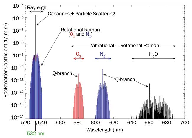
Figure 1. Lidar backscatter spectrum of air and exploitation thereof to measure air data. Courtesy of Airbus/M. Fraczek.
Measuring the relative air speed between an aircraft and the local atmosphere — true air speed — is the best known and easiest measurement for airborne lidar. The primary physical effect exploited in this approach is the Doppler shift, causing a frequency shift of the received backscattered light relative to the emitted probe beam (Figure 2). Frequencies are shifted to the blue for positive and red for negative relative speed. Since the Doppler effect only applies in the collinear direction to the probe beam (line-of-sight), a minimum of three optical probes providing air-speed measurements in three linearly independent directions are enabling the recovery of a full 3D airflow vector. From this, not only true air speed but also the angle of attack and angle of side slip (the horizontal angle between the aircraft’s body axis and its moving axis) can be derived.
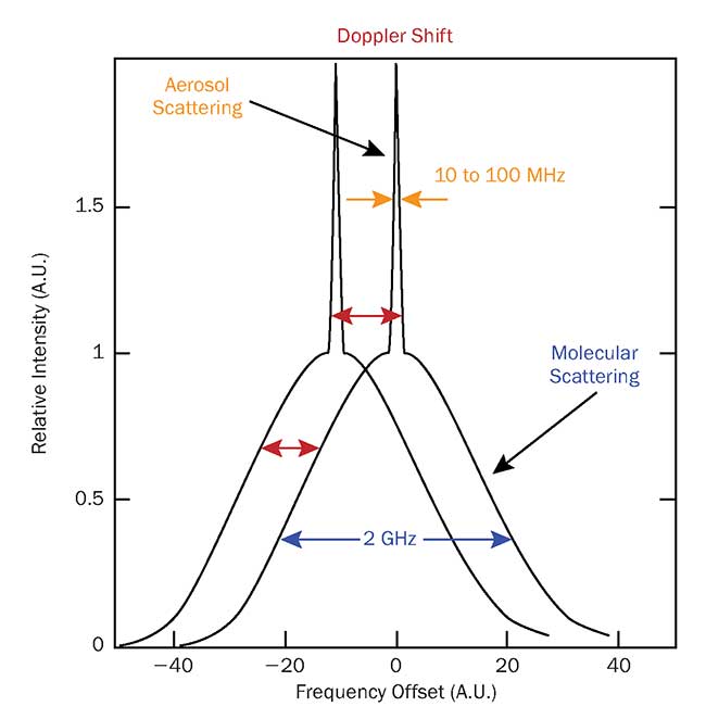
Figure 2. Aerosol scattering (thin peaks, can vary by 3 to 4 orders of magnitude in intensity) and molecular scattering (broad shoulders, can vary by a factor 3 to 4 in intensity). Doppler shift of the backscatter (red arrows) is directly giving the true air speed. Courtesy of Airbus.
There are two distinct approaches to optical air data measurements today. The first is coherent detection, exploiting Doppler-shifted backscatter from aerosols — dust, sand, dirt, particles bigger than or about the laser wavelength’s dimension: Mie backscatter. The detected backscatter signal is as narrow as the laser linewidth of the outgoing optical probe (see peaks with typical laser linewidth of 10 to 100 MHz in Figure 2). It allows the coherent frequency mixing of the outgoing and incoming signals, as well as direct measurement of the Doppler shift as the frequency difference in the mixing process. Coherent detection is very simple and sensitive; however, it is dependent on the aerosol particle concentration in the surrounding air flow. The concentration of aerosols is dependent on meteorological parameters and might decrease rapidly with altitude by 3 to 4 orders of magnitude between ground level and cruising altitudes. Continuous coherent detection is thus well-suited at helicopter altitudes, low flight altitudes and near to the ground, but not so for cruising airplanes. Applying a sophisticated event-triggered coherent detection mode1 — where a low number of aerosols can already generate a usable Doppler signal enabling air-speed measurement at high altitudes —
improves the situation, but without enabling a really predictable measurement rate and reliability.
The other approach, direct detection, is based on molecular, or Rayleigh, backscattering. The molecular concentration of air is very predictable and varies only by a factor of 3 to 4 between sea level and cruising altitudes. The drawback is a 2- to 3-GHz signal broadening of the detected signal, as compared to the outgoing probe, which is caused by rapid Brownian motion of molecules (see broad Gaussian base of about 2-GHz width in Figure 2). As such, a coherent frequency mixing is hardly possible, as it requires an optical frequency shift discriminating element. Modern approaches use either molecular absorption cells or fringe images from interferograms (the intensity distribution behind an interferometer that is detected with a camera) combined with image processing2 to determine the Doppler shift from changes in the fringe radius. In the case of interferograms, aerosol and molecular signals can be identified in the interferogram by the different width of the fringes (Figure 3).
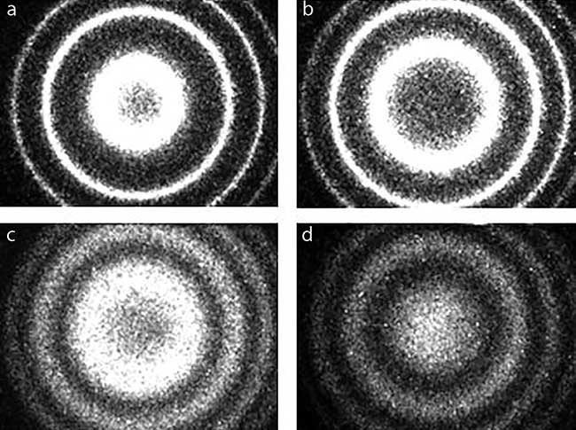
Figure 3. Lidar interferograms, taken during the AWIATOR flight test using a UV-camera-based detector, located behind a Fabry-Perot interferometer include: laser reference signal (a); in-cloud (strong aerosol) backscatter (b); mixed aerosol and molecular backscatter at lower altitude (c); and pure molecular backscatter at 39,000-ft flight altitude (d). See reference 2. Courtesy of Airbus.
Other air data, such as density, temperature, pressure and humidity, can be derived from molecular scattering (direct detection) only. Promising approaches exploit either the shape of recorded Rayleigh scattering signals or other scattering processes such as Raman scattering. There, the molecules are excited by the laser beam to rotate or vibrate.
The energy transfer to or from the molecules leads to a characteristic frequency shift of the backscattered light. Temperature measurements with 1K accuracy and humidity measurements with 1 percent accuracy (under relatively high humidity conditions) are straightforward to achieve. But a major challenge remains: measuring the air pressure and air density at the required 0.3 percent accuracy level3.
Results from the optical air data sensors’ flight test campaigns have been reported in scientific literature for many years. Both coherent detection and direct detection approaches can achieve the required true air speed accuracy of 2 knots. Several OADS suppliers are currently maturing prototypes and early results into products4. However, a trade-off needs to be found for the OADS measurement range. While shorter ranges offer a stronger backscatter signal and therefore lower laser power is required, a longer range is less affected by local air flow disturbance in the boundary layer of the aircraft. Normally, ranges discussed here are in the order of meters.
Forward-looking lidar
Lidar measuring at longer ranges delivers a much broader spectrum of additional information and advantages over equivalents of conventional air data measurements. Disturbing atmospheric effects such as shear wind, gusts, vortices and turbulence not affected by the aircraft itself can be measured by at least three forward-looking beams, even in absolute clear air as long as direct detection is applied. This is not possible to measure in a conventional way — not even by weather radar that’s normally used to detect turbulences. Forward-looking lidar can act as a laser radar, akin to radio frequency radar for clear air atmospheric phenomena.
Classical radar gives pilots a warning a hundred or more kilometers ahead, allowing for decision and reaction times in the range of minutes when flying at approximately 250 m/s. For lidar, such ranges cannot be achieved. First, atmospheric absorption and scattering at orders of magnitude larger in the optical wavelength ranges than in the radar frequency range limit the measurement range ahead of the aircraft. Lidar systems are far less sensitive than radar systems, due not only to lower probe powers and larger measurement bandwidths, but mainly because of the dominant role of shot noise, which is typically much higher than the thermal noise that dominates radar systems.
For ground-based lidar, these limits are partly compensated by long integration times on the order of minutes. In airborne applications, however, the vehicle speed requires update rates of roughly 10 Hz. Typical airborne lidar ranges are therefore limited to a few kilometers at relaxed accuracies, and a few hundred meters for high accuracy.
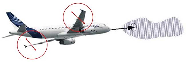
Figure 4. Aircraft being equipped with forward-looking lidar are able to counterbalance turbulence and gust influence (lift change, wing loads, accelerations) by deflecting control surfaces. Courtesy of Airbus.
This brings up the issue of whether or not human interaction is required at all. In the case of gusts, shear wind and turbulences, the aircraft can compensate for the atmospheric disturbances automatically, similar to how vehicles react when skidding. A lidar system that is directly connected to the flight control could allow for an advanced autopilot system, which actively measures and reacts to atmospheric disturbances. This counterbalances them by deflection of the conventional aircraft control surfaces (Figure 4). Such a feed-forward system would require accurate and reliable measurements of the air volume encountered by the aircraft, meaning that the air properties should not be sampled too far ahead. At distances of, for example, 50 to 100 m ahead of the aircraft nose, the disturbance will be encountered in about 0.3 to 0.5 s by the wings. This allows enough time for the flight control computer to calculate the corrective maneuver and apply the appropriate control signals — aircraft control surfaces have a deflection rate on the order of 30°/s; only some degrees of deflection are needed in cruise speed. This could lead to improvements in comfort in the aircraft, undisturbed service in the cabin and alleviation of the wing load and bending. It could also limit the impact of clear air turbulence, allow for fast response to wind shears and affect many other factors.
Airborne lidar could therefore be categorized into:
• Long-range systems with some kilometer range to warn pilots5 (not mature yet).
• Midrange systems with 50- to 200-m range to automatically apply correction maneuvers (autopiloting)2,6.
• Short-range systems with 0.5-m to a few meters range for pure optical air data sensing1,3,4.
Air speed, turbulence measurement
While short-range pure OADS systems are incorporated in products by several suppliers4, interest is turning to commercializing midrange systems. Coherent systems for near-ground helicopter applications and at lower altitudes have been demonstrated by several companies. One successful demonstration of a direct-detection midrange system in commercial aircraft came from Airbus some years ago: the AWIATOR project, funded by the European Commission2. An 18-kHz repetition rate laser at a 355-nm wavelength with a bandwidth below 100 MHz and an average UV power of 4 W was used, applying Fabry-Perot interferometer-based fringe imaging.
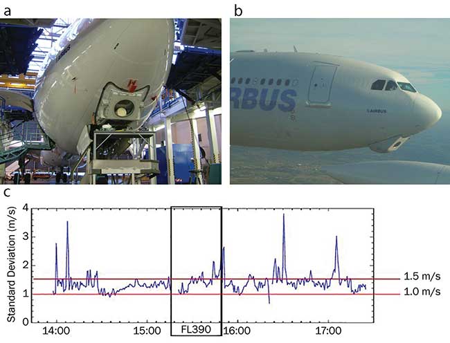
Figure 5. Airbus AWIATOR forward-looking lidar, installed (a) and flight tested (b) in an A340-300 aircraft inside a fairing, enabling direct forward laser beaming, looking 50 m ahead of the aircraft nose. Standard deviation of the true air speed measurement is mostly around 1 to 1.5 m/s without filtering (c) with maximum flight level of 390 marked (black box). See references 4 and 6. Courtesy of Airbus.
A true air speed standard deviation of 1 to 1.5 m/s was proven at update rates of 16 Hz for a full 4-beam vector at 50 m ahead of the aircraft’s nose (~70 m to wings) without periods of not measuring signals (Figure 5)6. In a next step, it would be required to connect such a system to flight control and demonstrate a full-loop automatic counteraction of atmospheric disturbances that includes gusts, shear winds and clear air turbulences.
If the beams are not fixed in a single direction but can be scanned appropriately, additional atmospheric perturbations such as wake vortices could be detected, as well7. This would allow partial corrective actions to their impact on flight dynamics (Figure 6). Should such a wake vortex detection and corrective system be accepted by aviation authorities to relax the safety margin in takeoff and landing spacing between aircrafts, the throughput of airports could be increased without increasing the number of runways.
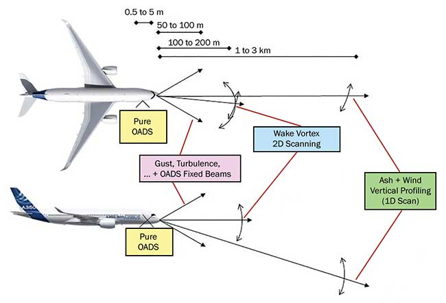
Figure 6. Very short-range optical air data sensor and three forward-looking lidar scenarios for gust and turbulence autocorrection (including OADS data) at typical 50- to 100-m range, wake vortex detection by 2D lidar scanning, and ash/wind profile altitude 1D scanning at typical 1- to 3-km range. Courtesy of Airbus.
Forward-looking lidar could thus allow for both optical air data measurement, as well as improved autopiloting functions as described. Furthermore, wind speed could be measured with a vertical scan of the lidar beams (Figure 6) for optimization of the flight level.
Detecting volcanic ash
The backscatter signal could be further analyzed to detect volcanic ash, as has already been demonstrated by DLR (German Aerospace Center) in scientific missions8, now in a forward-looking scanned mode to measure ash concentration versus altitude, avoiding volcanic ash-loaded flight levels. This data could indicate a safe situation — a suitable flight level, for example — and therefore help to continue air transport in case of volcanic ash incidents.
Although this situation sounds quite rare, volcanic ash events can be heavy and long lasting, causing large economic losses. In 2010, the eruption of the Eyjafjallajökull volcano in Iceland caused the largest air-traffic shutdown since World War II. The closures caused millions of passengers to be stranded not only in Europe, but around the world. With large parts of European airspace closed to air traffic, many more countries were affected as flights to, from and over Europe were canceled. The International Air Transport Association (IATA) stated that the total loss for the airline industry was around $1.7 billion9. Air traffic was shut down for about three days, since it was difficult to get exact, real-time ash measurements along the flight routes.
At that time, pilots had no volcanic ash sensors on board their aircraft. Future volcanic eruptions — from the Icelandic volcanos, for example, which are overdue for a heavy eruption — could lead to many weeks of ash contamination in the air. An onboard lidar ash sensor, capable of discriminating volcanic ash from biomass burning particles by polarization ratio discrimination, would allow safe operation in areas measured as ash free. This capability would keep the airspace open and optimize the flight routes wherever safe operation is possible. Other hazardous atmospheric particles such as supercooled large droplets or ice crystals might potentially be identified by such a lidar system.
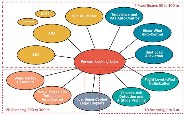
Figure 7. An overview of the potential different functions a multifunctional forward-looking lidar device could provide onboard an aircraft with indicated laser beam constellations (red boxes). Courtesy of Airbus.
Forward-looking lidar has the potential to become a very versatile instrument on aircraft (Figure 7). Assessing the full multifunctional benefits will be key to drawing the appropriate business case for ubiquitous implementation of optical air data sensors on commercial aircrafts.
A major challenge is that all of the lidar functions previously mentioned — air data measurement, autopilot support functions such as turbulence and shear wind balancing, load alleviation and ash detection — belong to separate Air Transport Association (ATA) chapters, in which aircraft development responsibilities are divided. In turn, this requires strong cross-ATA collaborations and a combined architectural approach for the integration of a multifunctional forward-looking lidar sensor on board commercial aircraft11.
Meet the author
Nikolaus P. Schmitt is senior expert of Optronic Systems at Airbus and holds a diploma in physics and a Ph.D. from Munich University. He has 30 years of professional experience in lasers, lidar and optical communications in aerospace and defense; email: [email protected]/[email protected].
References
1. M.J. Verbeek and H.W. Jentink (2012). Optical Air Data System Flight Testing. Report no. NLR-TP-2012-068, https://core.ac.uk/download/pdf/53034296.pdf.
2. N.P. Schmitt et al. (June 2009). A340 flight test results of a direct detection onboard UV LIDAR in forward-looking turbulence measurement configuration. 15th Coherent Laser Radar Conference, Toulouse, France.
3. M. Fraczek et al. (2013). Short-range optical air data measurements for aircraft control using rotational Raman backscatter. Opt Express, Vol. 21, Issue 14, pp. 16398-16414.
4. J. Croft (2016). Laser based air data systems come of age. Aviation Week & Space Technology. http://aviationweek.com/commercial-aviation/laser-based-air-data-systems-come-age.
5. P. Vranken et al. (2015). Flight tests of the DELICAT airborne LIDAR system for remote clear air turbulence detection.
The 27th International Laser Radar Conference, New York. https://doi.org/10.1051/epjconf/201611914003.
6. G. Jenaro-Rabadan et al. (2010). Airborne LIDAR for automatic feedforward control of turbulent in-flight phenomena. J Aircraft, Vol. 47, Issue 2, pp. 392-403.
7. D. Rees (2014). UV Imaging Lidar for Wake Vortex Detection. WakeNet Europe 2014 Workshop, EUROCONTROL Experimental Center, Brétigny, France.
8. U. Schumann et al. (2011). Airborne observations of the Eyjafjalla volcano ash cloud over Europe during air space closure in April and May 2010. Atmos Chem Phys, Vol. 11, Issue 5, pp. 2245–2279.
9. IATA Economic Briefing (2010). The impact of Eyjafjallajokull's volcanic ash plume. www.iata.org/whatwedo/Documents/economics/Volcanic-Ash-Plume-May2010.pdf.
10. N.P. Schmitt (2017). Research results, lessons learned and future perspective of forward-looking LIDAR for aircraft. CLEO Conference Laser Science to Photonic Applications, AM1A.2, San Jose, Calif. doi.org/10.1364/CLEO_AT.2017.AM1A.2.
11. N.P. Schmitt (2016). The use of photonics in aerospace – some perspectives 2020-2030. PHAROS Photonics, Aeronautics and Space Event 2016, Bordeaux, 24.10.2016.