The success of an automated machine vision system is determined by the effectiveness of the lighting and imaging system. A new illumination technique is helping to streamline image processing and analysis.
Leo Baldwin, and Karen Ronning-Hall
Automated machine vision systems are increasingly being used to perform inspection and identification tasks during production. They are more consistent and faster than humans, and only automated systems can meet many of the current expectations for process control and inspection. A specialized lighting and imaging system can greatly simplify downstream image processing and analysis.
A new technique for this purpose is under development at Electro Scientific Industries. Called narrow-angle dark-field illumination, it is particularly advantageous for highlighting minor features or defects on flat, shiny objects. Applications that stand to benefit from this technique include reading wafer identification scribe marks and inspecting chip-scale devices for chips and cracks after sawing.
Narrow-angle dark-field illumination provides the ability to read all types of scribe marks, no matter how small or “soft,” and increases productivity in reading large alphanumeric scribes, bar codes and 2-D identification matrix scribes, by using the same setup. It allows increased tolerances for object placement because the entire field of view is usable.
One way to optimize a vision system is to vary the location of the light source and the camera. In backlit systems, these are on opposite sides of the object. With the exception of the inspection of transparent articles and profiling objects in silhouette, the majority of machine vision systems employ front lighting, where the light source and the camera are on the same side of the object.
Dark- and bright-field light
Front-light illumination is categorized as either dark- or bright-field, depending on the appearance of the background image. Three factors affect whether an illumination scheme is bright- or dark-field: the light source, the lens that forms the image and the object itself.
The difference between dark- and bright-field illumination of a shiny surface, such as a mirror, is demonstrated in Figure 1. The angle between the left eye and the surface is not complementary with the angle between the light source and the surface, so the surface appears dark, except for scratches and dust that scatter the light and appear bright. The eye on the right is at a complementary angle to the light source and sees a bright surface; the dirt and scratches are only slightly less bright and are difficult to see.
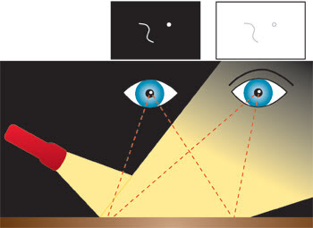
Figure 1. In dark-field and bright-field illumination, the eye on the left sees the surface as dark (dark-field) and the eye on the right sees the surface as bright (bright-field).
Dark-field illumination provides a way to highlight certain features with high contrast so that they are more visible on flat, shiny surfaces, such as a mirror. Increasing the intensity of the light source can improve the clarity of the features, and the shiny surface always appears dark.
Narrow-angle dark-field
In some applications, the best imaging occurs when the dark-field illumination is as close as possible to the bright-field illumination without quite making the field bright. We refer to this technique as narrow-angle dark-field illumination because the angle between the apparent source of light and the imaging system is narrow. If the light source is moved slightly to align with the imaging system, the illumination turns from dark to bright field.
Narrow-angle dark-field illumination is ideal for reading soft-mark identification on silicon wafers. During manufacture, the wafers are inscribed with a serial number for process tracking. Soft-mark scribes are made by gently heating a small spot on the silicon until it puddles and surface tension pulls the silicon into a shallow dish shape. The mark is made up of a matrix of these shallow pits. Soft-mark scribes are subtle and difficult to see.
The shallow pits behave like tiny curved mirrors with a long focal length. They bring incident collimated illumination to a focus, after which the light diverges, but only over a small angle. To illuminate them with adequate contrast, the light has to come almost from the camera lens, but not quite. If the light shines directly on the wafer along the line of sight from the camera lens, the wafer acts like a mirror and the light is reflected directly back into the camera (bright field). The marks also reflect most of the light back to the camera, with only a little bit lost because of scattering. The result is a low-contrast image: The wafer looks bright and the marks look only slightly less bright.
Narrow-angle dark-field illumination improves the contrast. The light comes in slightly from the side, the wafer appears black, and the pits appear bright. If the light comes in from too much of an angle, the pits also are dark and cannot be seen. The light must be within the small angle of divergence created by the pits, but outside any field angle of the lens.
In previous designs, this effect was created with a bank of lights placed just to the side of the optical axis and baffles placed where needed to keep the image of the lights out of the field of view. The baffles frequently occluded a portion of the field of view (Figure 2).
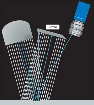
Figure 2. In this example of narrow-angle dark-field illumination, the small pit in the object scatters light over a narrow angle (blue rays). The light that does not hit the pit is reflected conventionally. Because the pit scatters light over such a small angle, the camera must be placed close to the optical axis, and a baffle must be used to keep the camera from “seeing” the illumination source (which would make the system bright-field). If the pit had less curvature, the light from the pit would also hit the baffle, and the pit would be invisible.
While this approach can be effective, it has shortcomings. Primarily, the angle between the incident illumination and the axis of the camera increases with the distance from the baffle, which causes a gradient in the contrast across the image. This problem can be mitigated by using two opposing banks of illumination and corresponding baffles. This cannot, however, eliminate the problem.
The conventional lens causes a secondary effect (Figure 3). With a divergent light source and a conventional lens, the angles between the light rays and the object and the imaging rays and the object both vary across the field of view, giving rise to gradients in the brightness of the object.
Figure 3. With a divergent light source and a conventional lens, the angle between the light rays and the object (blue) and the imaging rays and the object (red) both vary across the field of view, giving rise to gradients in the apparent brightness of the object.
These effects, when combined, create gradients across the field of view, and they degrade the performance of conventionally designed narrow-angle dark-field systems. These gradients generally are within the capabilities of the optical character recognition software, but as wafer manufacturers make the marks “softer,” smaller and closer to the edge of the wafer, conventionally designed systems are becoming inadequate.
A new approach
Electro Scientific Industries’ new approach to narrow-angle dark-field imaging achieves symmetry and uniformity across the field of view in a practical, compact system (Figure 4).
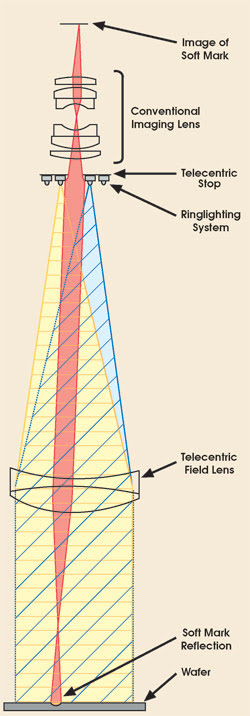
Figure 4. Electro Scientific Industries has developed a narrow-angle dark-field imaging system with this configuration.
Arriving at this symmetry and uniformity requires a design that meets three criteria:
• The illuminating rays must be parallel (collimated) so that the incident angle between the illumination and the object does not vary across the field of view.
• The image-forming rays must be parallel (telecentric) so that the angle between the rays and the object does not vary across the field of view.
• The lighting must be symmetric, preferably with circular symmetry, which highlights features such as the soft mark with closed, smooth curves; other shapes introduce additional edges that can slow down image processing algorithms.
The new design includes a telecentric imaging lens, comprising a conventional imaging lens and a telecentric field lens placed one focal length in front of the entrance pupil of the conventional lens. The telecentric field lens serves a dual purpose: It redirects and makes parallel the normally divergent rays from the conventional lens, and it collimates the illumination. If we had used a beamsplitter, we could have placed the illumination source at precisely the focal point of the telecentric field lens, but this would give us bright-field illumination. Instead, we placed a series of concentric ringlights (LEDs) on the telecentric stop; illumination of the ringlights can be adjusted to control the brightness, and rings of various diameters can be selected to control the sensitivity for different applications.
Light from the LEDs on the ringlight is collected by the telecentric field lens and collimated onto the object (Figure 4). Most of the light is reflected directly back up into the telecentric lens, where an inverted image of the LED is formed on the telecentric stop. Because the image is formed on the stop, the light does not get through to the camera, and the system is dark-field.
A feature, such as a crack or the pit of a soft mark on a wafer, scatters or refocuses the light (red). After the light scatters (from a crack) or passes through focus (from a soft mark, shown), the light continues to diverge until it encounters the telecentric field lens. Because this light is divergent rather than collimated, it cannot be imaged at the stop; instead, the light continues to fan out until it encounters the telecentric stop. The light is spread out enough that at least part of it spans the aperture of the telecentric stop and passes through the objective lens where the light is focused onto the image plane.
Given the geometry of the ringlight behind the telecentric field lens and coaxial with the telecentric stop, the angle between bright- and dark-field illumination can be almost arbitrarily small.
The imaging difference between a conventional dark-field system and the narrow-angle dark-field system is illustrated in Figure 5. The narrow-angle dark-field system clearly images the scribe marks and the process marks on the wafer. Scratches on the ruler are also visible, but they are not under the conventional dark-field illumination.
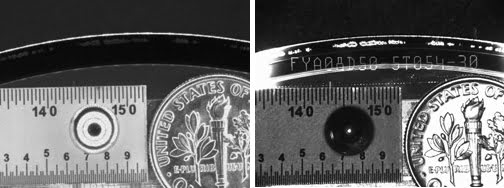
Figure 5. With conventional dark-field illumination (left) and narrow-angle dark-field illumination (right) the significantly improved imaging of wafer scribe marks (just below the arc of the wafer) are obvious. The objects include a ruler, a ball bearing and a dime on top of a wafer.
Adjusting sensitivity
The sensitivity depends on two system characteristics: the focal ratio (f number) of the telecentric field lens and telecentric stop, and the radius of the ringlight relative to the radius of the telecentric stop aperture. To eliminate moving parts, we chose to fix the telecentric aperture and to adjust the system sensitivity by using multiple concentric ringlights, with each ring individually controllable.
Illuminating the smaller-diameter ringlights increases the sensitivity of the system, in terms of both the angle over which light must be scattered to register on the imager and of the allowable tilt in the object before the system becomes bright-field, and the ringlight itself is seen in the field of view. There is an advantage to using sufficient sensitivity to see the features of interest (smaller ringlights) while desensitizing the system to background features that also may scatter light (for example, the devices on a wafer) and to tilts between the imaging system and the object plane (larger ringlights). These trade-offs are made during system setup, either manually or through a programmed illumination-optimization algorithm.
Eliminating internal reflections
The surface of the telecentric field lens facing the stop is concave toward the stop (Figure 4). If this surface were convex (which is typical for a lens with positive power), or even flat, a reflection from the surface would have negative magnification, and the reduced image of the ringlight would be reflected by this surface through the telecentric stop and into the imaging system. Our design constrains this surface so that the ringlight is imaged in reflection from it at a 1:1 magnification; the ringlight is imaged onto itself and blocked by the telecentric stop. By bending the telecentric field lens so that it is concave toward the stop, most of the internal reflections in the system can be eliminated.
Exploiting the properties of a telecentric lens for both illumination and imaging enables our narrow-angle dark-field illumination technology to achieve symmetry and uniformity across the field of view and is a high-contrast method for imaging minor features on flat, shiny surfaces. The ringlighting system provides a way to adjust sensitivity and contrast for different applications.
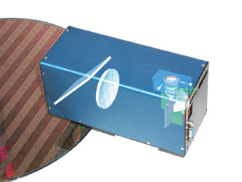
Figure 6. The narrow-angle dark-field system is being implemented in a wafer scribe reading system.
The telecentric stop blocks normally reflected rays from the illumination system, which creates the dark field without occluding the field of view, as the baffles did in previous designs.
Narrow-angle dark-field illumination technology is enabling the development of the next generation of identification reading, alignment and inspection systems that are more compact, less intrusive and less expensive than similar systems available today.
Meet the authors
Leo Baldwin is a senior research scientist at Electro Scientific Industries’ Vision Products Group in Portland, Ore. He holds nine patents in optics, lighting and machine vision.
Karen Ronning-Hall is a technical writer for Kaia Communications in Portland, Ore.