Laser manufacturing requires time-tested, reliable solutions.
Dr. Klaus Krastel, Trumpf Laser und Systemtechnik GmbH, David Havrilla, Trumpf Inc., and Holger Schlueter, Trumpf Photonics
The market for industrial laser systems is very mature and has been growing steadily for almost 30 years. In 1979, the first two-dimensional laser-cutting systems were introduced as tools for the fabrication industry. Today, this market has expanded from cutting to welding and from two- to three-dimensional applications.
Customers have grown to expect industrial solutions and are not typically concerned with the technology behind the solutions. They expect a semi- or fully-automated tool with an uptime greater than 95 percent, and proven processes and operating procedures. They are not focused on laser technology but rather on overall system performance.
This need for process and system performance has created a marketplace that is dominated by solution providers. A solution must include the process — usually encoded in technology tables within the machine — the motion system, beam delivery, programming software and the laser source. Typically, the laser source accounts for 25 to 30 percent of the value of such a laser-processing solution.
New beam delivery
Two-dimensional laser-cutting systems generated more then $4 billion in revenues in 2005. Interestingly, the machines are typically sold to fabricators with 10 to 20 employees. This means that the 2-D laser-cutting process has become so standardized that a small job shop can purchase the machines without undertaking extensive operator training or possessing complicated programming experience.
Three-dimensional laser cutting and welding systems require more know-how in the programming of the tool path, as do five-axis milling machines and spot-welding robots. Similar to a five-axis milling machine, modern 3-D laser cutting and welding systems use cartesian five-axis motion systems and achieve tool path accuracies of under 1/1000 of an inch (Figure 1).
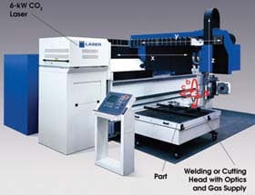
Figure 1. This laser machining center has a cartesian five-axis motion system and a 6-kW CO2 laser. These are labeled X,Y,Z for the linear axes and B,C for the two rotational axes.
A cartesian five-axis motion system is characterized by three linear axes of motion that are perpendicular to each other and two rotary axes that enable positioning of the welding or cutting head normal to any desired surface on the workpiece.
In contrast, a robot typically has six axes of motion, all rotational (Figure 2). To achieve a movement and orientation in cartesian space, the robot’s controller must solve a complex equation in real time, transforming the coordinates X-Y-Z and the orientation of the tool tip into the angles of the six rotational axes. This transformation can sometimes have more than one solution, and the robot’s controller must decide which one is better suited to a given situation.
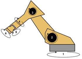
Figure 2. A robot has six axes of rotational motion.
By solving this equation, a robot can situate a beam in the same position and with the same orientation as a cartesian five-axis motion system. However, as soon as it needs to follow a path (during welding, for instance), the inertia of some and the motion of other individual axes makes them strongly interfere with each other. It then becomes impossible to solve the extended equation — which takes into account angular overshoot of the rotational axes because of varying inertia — with high accuracy. The result is that the path accuracy of a robot is fundamentally less than that of a cartesian five-axis motion system.
In general, robot-based laser processing solutions are limited by three inadequacies:
1. The path accuracy of a robot is not adequate for modern manufacturing requirements. For instance, circles and similar geometric shapes typically do not meet customer demands.
2. A robot heats up during operation and cannot achieve the same positioning accuracy over long manufacturing periods as can a cartesian five-axis motion system.
3. Positioning and processing speeds of robots are well below those of modern cartesian five-axis systems.
Cartesian five-axis motion systems are mainly used in cutting applications, where superior speed, and position and path accuracy are required. However, they tend to be substantially more expensive than robot-based systems, so the total addressable market is limited to high-value applications.
For high-volume, medium-value welding applications — for instance, most automotive welding applications — the first two deficiencies of robot-based systems are less relevant and have allowed for a laser market of a few hundred million dollars for robot-based 3-D laser welding systems.
In this market segment, laser powers have been steadily increasing over the past few years (from around 3 kW in 1998 to 8 kW in 2007), and this has pushed the welding process speeds to values where the robot’s No. 3 deficiency — its speed (see above) — becomes the most important obstacle to increasing throughput and productivity.
These stumbling blocks have led to the development of a new beam-delivery solution for welding applications. Recently, two techniques were realized that eliminate the need for the fast and accurate mechanical axis of a cartesian five-axis machine and that utilize high-power scanning optics to position the beam within the work envelope. The industry has termed these beam scanning systems “remote laser welding” stations.
These systems greatly reduce the time it takes to position the beam between two welds, increasing the beam-on time, and also allow maximum process speeds, even when enabling complex path geometries with small radii
Remote laser welding
The first new approach is a remote system for a 6-kW CO2 laser (Figure 3). The system consists of the laser source on the far right and the beam delivery and scanning system extending over the work envelope. The configuration shown has two separate work zones, enabling better productivity by alternating laser welding and part loading and unloading between the two work zones.
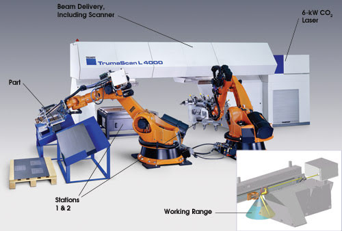
Figure 3. This CO2 laser remote welding system has a 6-kW laser and two workstations.
Part loading and unloading can be accomplished via different methods — dial table, robot, linear transfer. The system shown in Figure 3 uses robots to pick up the parts and to hold them in place under the scanning system. During processing, the laser beam focus is adjusted up and down by moving the focusing mirror (focal length: 1.5 m), while the X-Y positioning is achieved by deflecting the now-converging beam with a mirror on a kinematic mount that allows deflection of up to 30° in both directions.
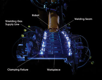
Figure 4. Specialized fixturing holds the workpiece for laser remote welding with a 6-kW CO2 laser.
Figure 4 shows the workpiece held in place by the robot, while a long-exposure photograph allows visualization of the laser beam path along the weld seams. An important aspect of remote laser welding is that the welding shielding gas must be supplied through the part fixturing. Clearly visible in this picture are the gas supply hoses running past the clamping mechanism with the yellow knobs. This is a departure from highly flexible no-tooling laser processing solutions, as it necessitates dedicated fixtures for remote laser welding. However, this is a price the industry is willing to pay for the increased productivity provided by a remote laser welding system.
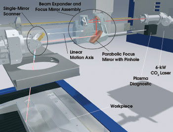
Figure 5. The internal optics of this remote-welding station allow the beam power to be delivered anywhere within the work envelope.
Figure 5 shows a schematic of the normally enclosed beam path. The laser beam exits the 6-kW CO2 laser parallel to a linear-motion axis. Two separate optical assemblies can move parallel to the linear-motion axis:
1. A beam-expander and focus-mirror assembly.
2. A single-mirror scanner assembly.
The beam-expander and focus-mirror assembly consists of three mirrors: a parabolic focus mirror and two that form a beam-expanding telescope. The parabolic focus mirror is crucial for consistent process results. Although a lens could potentially achieve the same focal length and spot diameter as a parabolic mirror, transmissive optics experience major thermally induced focal shift when the 10.6-μm laser power changes. It is typically not possible to compensate for such focal shift, which also depends greatly on the age of the optics and on the degree of contamination.
The parabolic mirror solution has another advantage: It allows for gathering the process light through a center hole for plasma diagnostics.
After passing through the beam expander and focus mirror assembly, the convergent beam hits a single-mirror scanner that deflects the beam in the X- and Y-directions. At the beginning of an operation, the single-mirror scanner assembly moves to a predetermined position over one of the workstations. (Figure 3 shows a system with two stations, but up to four stations are possible.) It can stay fixed, while the parabolic focus mirror adjusts to provide very fast Z-axis motion of the laser beam focus. When angular motion of the single-mirror scanner is added to the focal-length adjustment, the system can address any position within the work envelope.
The second approach to remote laser welding is a system that — unlike the variable-focus one discussed above — relies on coarse and fine position adjustments. The coarse adjustment is performed by the robot arm, and the fine adjustment is achieved with the programmable focus optics.
The system shown in Figure 6 uses a 4-kW thin-disk laser, but powers up to 8 kW will soon be commercially available. A beam switch inside the laser housing can switch the laser output among several workstations, and the beam is delivered to the stations via an optical fiber.
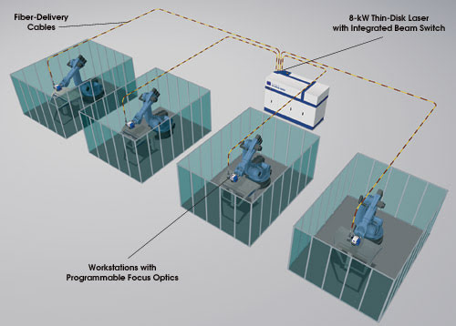
Figure 6. A laser network enables time-sharing in a remote welding application.
Although reflective optics were necessitated by the 10.6-μm radiation of the CO2 laser in the previous example, transmissive optics are well suited for the 1.06-μm radiation from the thin-disk laser because the absorption of the radiation in the quartz optics is many orders of magnitude lower. Therefore, there is no thermally induced focal shift, and it is even possible to use beamsplitters to enable plasma diagnostics.
The coarse movement of the robot arm must be synchronized with the fine movement of the programmable focus optics. The position-feedback loop of a robot is usually updated at 500 Hz, which is far too slow for accurate synchronization between the robot motion and the motion of the scanner in the programmable focus optics.
Therefore, a robot-based remote laser welding system typically includes an enhanced robot/scanner control that allows better path accuracies and also enables the concurrent movement of the robot and the scanner, which is crucial to efficient production. The system would be far less efficient if the two motions had to take place sequentially.
The beam switches that are integrated into modern solid-state lasers — such as in the networked stations shown in Figure 6 — permit two major improvements over single-laser workstations:
1. The beam of one laser can be time-shared between different stations.
2. In the case of scheduled maintenance, a second laser can provide redundancy for the laser that is out of commission.
This switching capability has been a huge part of the success of the solid-state lasers in automotive welding.
Looking to the future
Modern remote laser welding systems enable new welding applications because of drastically improved productivity and speed. In recent years, stationary systems based on CO2 lasers and robot-controlled systems using solid-state lasers have been introduced into the industrial marketplace. They provide excellent performance and flexibility, while providing the possibility of online quality control through optical process monitor capability. Remote laser welding is the latest in a series of successful industrial laser solutions that have revolutionized sheet metal processing over the past 30 years.
In the future, this technology will lay the groundwork for further innovations in cutting and welding.
Meet the authors
Klaus Krastel is an R&D engineer for application development Laser and Systems at Trumpf Laser und Systemtechnik GmbH in Ditzingen, Germany, and is responsible for CO2-remote welding; e-mail: [email protected].
David Havrilla is the YAG product manager at Trumpf Inc. in Plymouth, Mich.; e-mail: [email protected].
Holger Schlueter is general manager and vice president of Trumpf Photonics in Cranbury, N.J.; e-mail: [email protected].