Modeling the impact of atmospheric turbulence on the beam path could illustrate the benefit of active wavefront-aberration correction using adaptive optics.
Dr. Allan Wirth and Jeff Yorsz
Bidirectional laser communications among ground and air- and spaceborne platforms holds promise of extremely high bandwidth data transfer in commercial and military applications. One challenge still to be met is optical-beam degradation from atmospheric wavefront distortion. Adaptive optics could help solve the problem, but identifying and understanding the parameters that define system performance is vital.
In general, laser communications system configurations are ground to ground, ground to air, ground to space and air to space. We will focus on simulation related to the air-to-space link because it is here that the benefit of wavefront correction is most controversial.
Anytime light propagates through a turbulent medium such as the atmosphere, it acquires wavefront errors. From an aircraft-to-spaceborne platform, the uplink and downlink problems require separate consideration because the atmospheric effects on propagation differ with direction. And, because the density of the atmosphere declines rapidly with altitude, most wavefront errors develop close to the aircraft.
Based on the Fried analytical model of the atmosphere proposed in the 1960s, for the altitudes of interest, the effective distance of turbulence from an aircraft is about 3 km.1 For the light propagating upward from the aircraft, the wavefront errors initiated close to it evolve along the travel path so that the beam reaching the satellite has both phase and intensity errors.
According to the eikonal equation describing this behavior, the change in intensity between two planes perpendicular to the propagation direction is proportional to the product of wavefront curvature and propagation distance.2 This effect is the source of scintillation in the beam. For light traveling down to the aircraft, though, the situation differs. The wavefront has only 3 km to evolve before reaching the receiver and, thus, is almost purely a phase error without any scintillation, making the airborne-to-spaceborne direction perhaps the most problematic link.
Modeling the atmosphere
The first step in assessing this communications link involves developing a model of the atmosphere, especially the turbulent layer of the tropopause (Figure 1). Key information will include determination of the range of altitude for the tropopause and modeling of jet-stream effects, especially because the communications link must operate even if the aircraft is below the tropopause and a strong jet stream is traversed at some zenith angles.
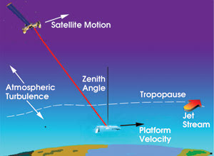
Figure 1. Modeling allows the determination of turbulence profiles for various aircraft-to-satellite communications link pathways.
It also is important to determine turbulence profiles along various link paths based on parameters such as aircraft altitude and velocity, and satellite altitude and orbital path. The aircraft altitude determines the starting point of the link path. Velocity sets the rate for laser beam translation through the atmosphere. The satellite altitude and path determine the beam’s apparent slew rate. Working with link paths defined from these parameters, engineers can use the atmospheric model to create a series of phase screens at different altitudes and put the data into wave optic propagation code to calculate the effects on the beam.
Additional input to the propagation code is the aero-optical effect of the flow field around the window of the transceiver on the aircraft, which can be modeled as a time-varying phase screen. This screen’s parameters must come from computational fluid dynamic modeling of the flow field. Although related code is quite complex, it is often available from large-airframe manufacturers. The results of this simulation of the communications link are a time sequence of phase and intensity maps for the entrance apertures of the two receivers.
Pointing errors
The atmospheric model also allows examination of other compensation-related aspects, such as point-ahead tracking. Because of the long path to the satellite, the light travel time becomes significant. This means that one must point the transmitted beam ahead of the satellite’s apparent location, just as a hunter must aim his gun ahead of a flying duck.
Difficulties arise when the point-ahead angle, which is typically tens of microradians, is larger than the isoplanatic angle of the atmospheric turbulence over which aberration is correlated. In such cases, the wavefront error measured from a source colocated with the satellite does not correctly represent the aberrations along the beam path. Because tilt is the strongest atmospheric aberration, this anisoplanatic effect can lead to serious pointing errors if the tracking algorithm uses only the satellite’s apparent position to estimate the error.
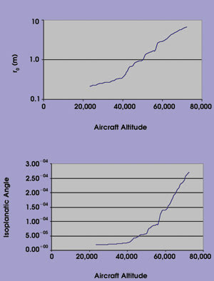
Figure 2. This turbulence model involving a 1550-nm beam illustrates the atmospheric coherence length (Fried’s r0 parameter) and the coherence or isoplanatic angle. For altitudes below the troposphere, coherence length is comparable to or smaller than potential transceiver aperture sizes, so significant atmospheric aberrations are expected.
To begin simulating the link to a satellite, Adaptive Optics Associates Inc. constructed a model atmosphere by modifying the Fried model to include the observed “bump” in turbulence in the tropopause and the strongly layered structure of turbulence. This model helped the engineers estimate integrated turbulence along a vertical path from aircraft at various altitudes.
The results for one realization of turbulence, made using a 1550-nm wavelength, include the atmospheric coherence length (Fried’s r0 parameter) and the coherence or isoplanatic angle (Figure 2). For altitudes below the tropopause (about 45,000 feet, in this case), the analysis showed that the coherence length is comparable to or smaller than potential transceiver aperture sizes. Hence, significant atmospheric aberrations should occur at these altitudes. In addition, the isoplanatic angle there is in the range of tens of microradians. Because this is comparable to the point-ahead angle required for a link to a satellite in low Earth orbit, tilt anisoplanatism is likely an issue as well.
Simple wave-optic simulations helped in further quantifying the impact of this level of turbulence on a free-space link. Using a Cn2 value representative of the index of refraction, a 1 x 1-m phase screen was generated for an aircraft altitude of 35,000 feet, subsections of which were extracted to simulate the motion of the aircraft past the turbulence.
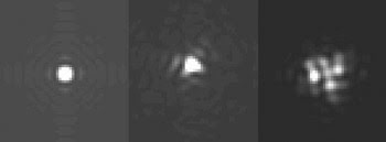
Figure 3. Compared with the diffraction-limited profile to the left, the center satellite beam profile shows little power loss from aberration. The right one indicates that significant fade events can occur because the receiver aperture could lie within a beam’s dark regions.
In this simple model, the turbulence itself was frozen in time. The extracted phase screen was then applied to a uniformly illuminated circular pupil 150 mm in diameter, and the resulting wavefront propagated to a range of 1000 km. While use of a single-phase screen did not model the real three-dimensional distribution of the turbulence, it provided a rough idea of the effects of turbulence on the beam pattern at the satellite.
This modeling process generated a sequence of 576 beam profiles. For a platform velocity of 200 m/s, the sequence represents about 0.1 s of flight time (Figure 3). The model then calculated the temporal variation of the received power for this sequence and found one fade event of about 10 dB for the data set (Figure 4).
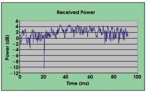
Figure 4. Calculation of temporal variation of the received power for a modeled sequence of 576 beam profiles indicates one fade event of about 10 dB for the data set.
Next, the scientists examined the atmosphere’s effect on beam pointing. For each profile, they calculated the location of the centroid of the light and found that the root mean square variation in pointing direction was slightly larger than the diffraction-limited beam radius and thus required correction to maintain adequate link signal.
To begin to determine the parameters for a compensation system, the scientists examined the spatial frequency content of phase aberrations by decomposing extracted phase screens into Zernike polynomials and determining temporal fluctuations of coefficients (Figure 5). Two tilt terms and one defocus term contain the bulk of the aberration, which is typical of all atmospheric aberrations. Correction of just these three terms would produce a beam that statistically should have power density close to the diffraction limit.
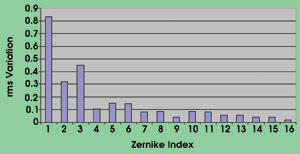
Figure 5. To help develop a compensation system, the spatial frequency content of phase aberrations was examined by decomposing extracted phase screens into Zernike polynomials and determining coefficient temporal fluctuations.
For typical imaging or directed energy applications, this is the figure of merit used to assess the degree of compensation. A communications link, though, requires somewhat different metrics. Correction of tilt and defocus would not prevent significant fade events in a satellite beam profile when the receiver aperture is within a beam’s dark regions. Because the turbulence is a random process, there will be occasions when higher-order aberrations are strong enough to disrupt the beam profile. More work is needed to properly assess their effect on the communications link. This, in turn, will affect the bandwidth requirements of any correction system.
Systems for correction
Use of adaptive optics to correct for wavefront aberrations has been successful in astronomy, ophthalmology and high-energy laser applications, and it is hoped that simulation will indicate the benefit of this technique for air-to-space laser communications.
One example of a general aberration correction system has a Hartmann-style wavefront sensor with an array of small lenslets defining the number of system subapertures (Figure 6). This is where the system samples the incoming wavefront and images the results onto a camera system. For this purpose, Adaptive Optics produces arrays of purely refractive lenses called monolithic lenslet modules, which have individual lenses as small as 25 μm. One advantage of such refractive optics is that the lenses can work with white light and with monochromatic light. Modules can be circular, square, rectangular, hexagonal or even more complex shapes with full edge-to-edge lenslet contact to maximize fill factor. The location of the focused spot within each subaperture determines the wavefront error of the incoming beam.

Figure 6. In a conventional compensation system, r0 generally determines the size of the subaperturesbecause it is indicative of the spatial variance of theturbulence. Beam tilt defines a dynamic range and will determine the number of subapertures.
The key parameters for each component derive from the results of the wavefront propagation modeling. For example, r0 generally determines the size of the subapertures because it is indicative of the spatial variance of the turbulence. The beam tilt defines a dynamic range and will determine the number of subapertures, while the temporal component of the atmosphere will determine the necessary frame, processing and mirror slew rates.
While data from the atmospheric modeling will be used to define the correction subsystem requirements, the system link budget and parameters will be required to meet the overall system performance goals. Critical parameters such as the beam pattern gain, coupling efficiency into the receiver fiber, and the depth and frequency of occurrence of link fades must be calculated, both for the uncompensated path and with compensation enabled.
The subsystem requirements will then flow down to the component parameter level. For this application, the newly emerging technologies of micromachined deformable mirrors and CMOS sensors will be beneficial because size and power needs will be significantly lower than those of more traditional technologies.
Adaptive Optics has deployed systems ranging from 69 subapertures operating at a 400-Hz frame rate to more than 2000 subapertures operating at 10 kHz. Research will continue in this area.
References
1. D.L. Fried (1966). JOURN. OF OSA, 56, p. 1380.
2. M. Born and E. Wolf (1980). Principles of Optics. Pergamon Press, Oxford, p.112.
Meet the authors
Allan Wirth is chief scientist and Jeff Yorsz is president and general manager at Adaptive Optics Associates Inc. in Cambridge, Mass.