Advancements in smart control technology enable optimal use of modern laser sources and help to leverage cost savings for industry.
Harald Vinçon, Sonja Kauer, and Maximilian Heym, SCANLAB
Considerable advancements have been made in the precision and dynamic control of laser scan systems during the last few years. Depending on the application, new control methods can bring additional productivity to users in fields such as microstructuring, bitmap processing, and display fabrication.
When fabricating and laser processing products, quality and process time are key criteria and often have to be weighed against each other when gauging efficiency in production. Intelligent RTC control boards for controlling scan systems can help to optimize micromachining processes.
The highest possible precision is essential in micromachining, bitmap processing, and display manufacturing. The control methods described below use electronic control boards to enable optimal results. They also introduce new functions that reduce total process time through elimination of nonproductive phases.
Optimized processing of surfaces
Micromachining applications for scan systems are diverse in functionality, depending on the industry in which they are used (Figure 1). Process speeds with maximized precision are essential when making molds, when manufacturing tool surfaces for the automotive industry, or when structuring wafers. Laser-based micromachining of materials is achieved by marking dashed lines, mostly made of collinear vectors. Because overlapped bidirectional marking is intended, exact positioning is required.
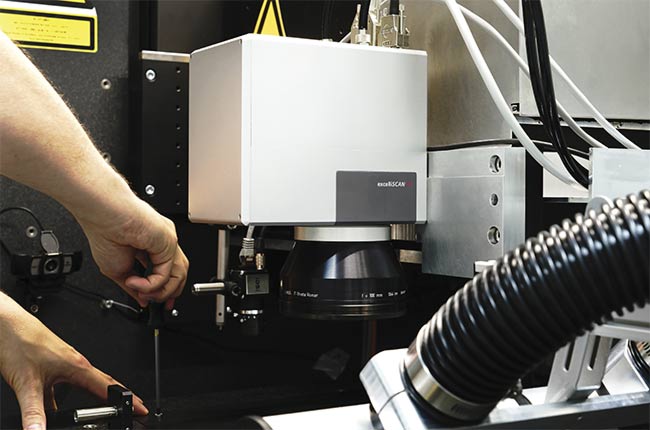
Figure 1. A scan head integrated in a laser processing machine for micromachining tasks. Courtesy of SCANLAB.
To achieve a homogenous energy deposition along the dashed lines’ entire length, equidistant laser pulse spacings based on a constant speed within the marked lines are essential. The “skywriting” approach substantially improves laser pulse positioning accuracy and homogenous energy deposition, but this technique lengthens process times considerably in many cases.
During jumps from one marked line to the next, the skywriting algorithm outputs compensatory scan head motions that guide the laser to the necessary position at the required speed for the next marking step.
The additionally generated jump commands increase process time significantly. Another undesirable effect is frequent acceleration and deceleration steps that can produce unwanted heating of the scan system, particularly during highly dynamic 3D marking processes over a long period.
Mark vectors and jump commands
For exact markings with minimized process time, a method of dashed line marking was developed, called short-vector processing (SVP). The technique optimizes marking of short vectors by analyzing multiple consecutive vectors and bundling them, when possible, into a single path. But bundling mark vectors can be complicated, depending on the situation. If a user wants a dashed line defined by a specific mark-jump-mark sequence or a polygon traversal (i.e., a mark-mark sequence), the first step is to test for collinearity of the individual vectors and jump motions.
Here, the system compares directions of two jump-separated mark vectors (or two mark vectors following each other in one polygon course). If the direction vectors of both consecutive marks do not differ within a predefined limit, these vectors will be regarded as collinear, or on the same path. In such a case, it’s assumed that the scanner can track the contour, and thus no extra skywriting motion is required. If the algorithm classifies consecutive mark vectors as noncollinear, a skywriting motion will be inserted between the two marks as usual (Figure 2).
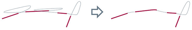
Figure 2. Classic skywriting versus short-vector processing: Short vectors with only marginally differing direction vectors can be processed in a continuous motion. Courtesy of SCANLAB.
Several specific criteria exist to determine whether two vectors can be regarded as collinear. One such parameter is the angle between the vectors’ directions (e.g., not exceeding 3°) and a minimum jump duration of 10 µs. Using an RTC board with SVP functionality reduces scanner motion to the necessary minimum when structuring dashed lines, thus measurably reducing process times, depending on the structure itself.
This technique is used, for example, by 3D-Micromac AG’s laser micromachining systems. Its applications range from selective structuring of PERC (passivated emitter and rear contact) solar cell passivation layers to fabrication of print and mold plates, where the laser performs deep etching with micrometer accuracy (Figure 3).
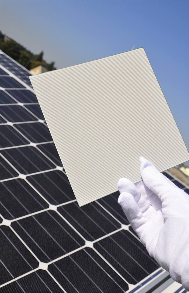
Figure 3. Damage-free laser-based ablation of a PERC solar cell passivation layer. Depending on the contact openings’ structural geometry, throughput reaches up to 3800 wafers per hour. Courtesy of 3D-Micromac.
Interplay between laser, scan head
Every marking sequence is preceded by an acceleration phase and followed by a deceleration phase in which the laser is off. To ensure the exact positioning of markings, the SVP algorithm makes full use of the RTC’s laser signal resolution capabilities. This method is ideally suited for dashed lines (Figure 4).
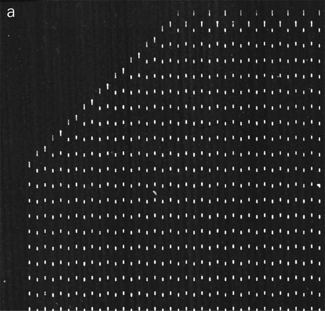
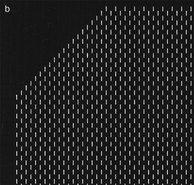
Figure 4. Marking result before (a) and after (b) optimization with short-vector processing and resolved laser delay overlaps. Courtesy of SCANLAB.
Compared to micromachining via skywriting alone, combining it with SVP at comparable accuracy can radically improve process time. For example, for a wafer with 301 individual 0.5-mm lines spaced 0.5 mm apart at 30 m/s scan speed, the process time shrinks by a factor of 28. This occurs without any loss of quality (Figure 5).
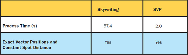
Figure 5. Comparative wafer process times using skywriting and short-vector processing. Courtesy of SCANLAB.
Highest accuracy in shortest time
The SVP functionality was initially limited to marking patterns with line durations of at least 10 µs. For specific applications involving even smaller structures, SVP’s advantage over classic skywriting was negligible.
This changed with the development of subcycle switching (SCS) on the RTC6. Subcycle switching allows up to 10 laser-on and laser-off commands per 10 µs — with an accuracy of 15.6 ns.
If even finer structures are required — for example, as short as 0.25 mm at
30 m/s scan speed — the jump duration is reduced to 8.3 µs and the limitation of at least 10 µs is no longer met. In this case, SVP — without subcycle switching — has to insert skywriting sequences for every gap to realize all vectors properly, and, as a result, the process time is almost doubled. Therefore, compared to conventional skywriting processing, SVP no longer offers an advantage.
Only by the addition of subcycle switching can the full performance gain of the SVP algorithm be achieved as before (Figure 6).
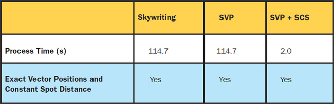
Figure 6. Comparative process times using various methods for marking wafers with structures of 0.25 mm. Courtesy of SCANLAB.
Ultrafast pixel images created
Graphic objects can be marked not only using vector commands such as dashed lines, but also via grayscale pixel images (bitmaps). Pixel images are created line by line and consist of a defined number of equidistant pixels. Marking is executed in one pass for an entire image line at a constant laser spot speed. Each pixel is processed by triggering an individual laser pulse with selectable pulse energy corresponding to its grayscale value.
SCANLAB developed the ultrafast pixel mode (UFPM) to increase the pixel output frequency. Prior to the use of this technique, pixel output frequencies of 800 kHz were sufficient in most cases. But certain applications — such as bidirectional marking in circuit board exposure or surface treatment of thin-film solar cells — have more demanding requirements. With UFPM, pixel output frequency is now available at up to
3.2 MHz. This quadrupling of pixels per time unit offers users increased accuracy and time savings.
Evenly distributed pulses for cutting
Displays and protective windows are examples of products manufactured using laser systems for precision cutting. A potential problem with glass cutting is inhomogeneous energy deposition, which can cause thermal expansion and microfissures. And, with such glass cutting, high contour accuracy is required.
One way to mark cut edges with the required accuracy and equidistant spots is skywriting combined with conventional beam sources and fixed-pulse frequencies. But here the expenditure of process time is disproportionately high.
Modern pulse-on-demand lasers, combined with the new spot distance control (SDC) function of the RTC6, enable control of the spot distance directly. This approach also requires a scan system equipped with SCANahead control technology. Using the position feedback signals, the RTC6 can trigger the laser at precisely the right time to achieve equidistant laser spots (Figure 7). Unlike marking with skywriting, with this method the process can be sped up because the laser processing can be active, even during acceleration and deceleration phases along the path.
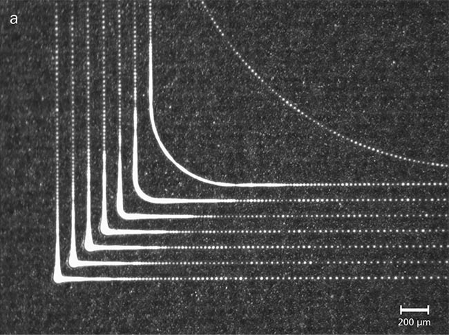
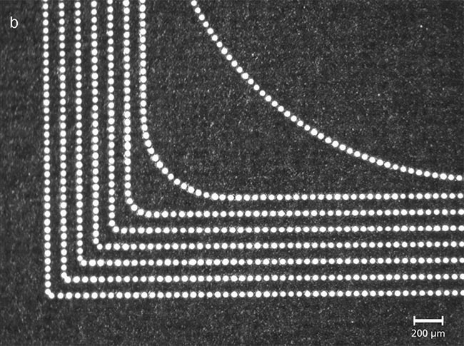
Figure 7. High-precision and equidistant laser pulses, marked with
varying speeds. The spot velocity at the corner points is 0, 100, 200, 400, 800, 1500, 3000, and 6000 mm/s (from outside to inside). The process executed without spot distance control (a) and with spot distance control (b). Courtesy of SCANLAB.
Optimization via smart control
Short-vector processing, subcycle switching, and spot distance control are valuable ways to optimize industrial fabrication marking processes, particularly in terms of process time. Ultrafast processing of pixel-based commands, too, can save precious process time while also increasing mark accuracy. Ongoing advancements in scanning control technology allow optimal use of modern laser sources and offer savings potentials for industries such as automotive, consumer electronics, and photovoltaics.
Meet the authors
Harald Vinçon joined SCANLAB in 2008, developing FPGA (field-programmable gate array) and DSP (digital signal processing) firmware. Since 2017, he has managed the embedded software team and is responsible for the development of new innovative control concepts. Vinçon studied electrical engineering and information technology; email: [email protected].
Sonja Kauer joined SCANLAB in 2011 as a software/firmware developer. Her main tasks include the further development of laser control features and short-vector processing. Kauer studied electrical engineering and information technology; email: [email protected].
Maximilian Heym joined SCANLAB in 2019 as product manager for software, control, and calibration solutions. He received a Bachelor of Science degree in electrical engineering and a Master of Science degree in photonics; email: [email protected].