To bring photonic crystals to commercial applications, researchers are working with optical design tools.
Dr. Michael J. Steel, RSoft Design Group Inc. and the University of Sydney,and Dr. Benjamin J. Eggleton, Peter Domachuk and Hong Nguyen, University of Sydney
Research into photonic crystals has been in vogue for some time, but real commercial use of these materials has yet to be demonstrated. The keys to their eventual success as a platform for integrated photonics lie in the exploration of new materials and the incorporation of additional functionality. Another critical component is the close interaction in research labs among fabrication, measurement and modeling.
Research at the Centre for Ultrahigh-bandwidth Devices for Optical Systems (Cudos) at the University of Sydney in Australia exemplifies these three aspects and is enabled by a simulation program that relies heavily on software from RSoft Design Group Inc. of Ossining, N.Y. We have chosen to concentrate on air-silica photonic crystals through novel uses of photonic crystal fibers. Although this low-index-contrast system does not support complete photonic bandgaps, it nevertheless displays a large number of useful and interesting properties.
Photonic crystal fibers are optical fibers with a lattice of holes (Figure 1a). They have attracted attention as a result of their novel dispersive and nonlinear properties and applications, such as efficient supercontinuum generation.
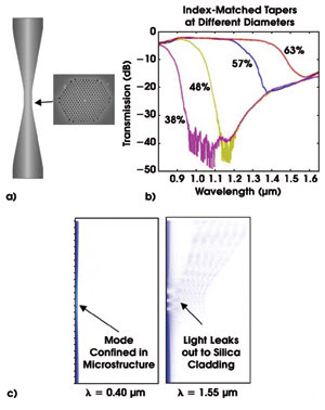
Figure 1. A schematic of a tapered photonic crystal fiber shows the photonic crystal cross section (a). In an illustration of measured loss in tapered photonic crystal fibers, transmission is plotted as a function of wavelength. The loss edge moves to shorter wavelengths with decreasing diameter (b). The software tool predicts confinement at short wavelengths and leakage at long ones (c).
At Cudos, we use flame-brushing techniques to taper the fibers to as little as 10 percent of their original diameters — or just 10 μm across. Fiber tapering also enables a high degree of control over dispersion, enhancing certain nonlinear effects. Reduction of the already-small core diameter further lowers nonlinear thresholds.
When measuring the transmission through photonic crystal fiber tapers, we observe a sharp transition to high loss at long wavelengths (Figure 1b). The loss edge shifts to shorter wavelengths with decreasing diameter of the fiber. From other experiments, we know that the tapering preserves the crystal microstructure. Hence, this loss imposes a limit on the rate at which a fiber can be tapered and still guide light usefully.
Fundamental mode
The cause of this loss is peculiar to photonic crystal fibers: a so-called “cutoff” of the fundamental mode of the fiber. The fundamental mode is the simplest spatial pattern in which electromagnetic waves can travel down the fiber. In conventional fibers, it can propagate at any wavelength. In photonic crystal fibers, however, it is guided with low loss only for sufficiently short wavelengths. At long wavelengths, the fundamental mode occupies the entire fiber, rather than just the core.
In a truly adiabatic photonic crystal fiber taper, the expanded core mode would propagate along the taper without coupling into higher-order modes of the fiber, and the fiber would display low loss. However, the photonic crystal fiber has a high density of cladding modes, with effective indices close to the fundamental. This raises the likelihood that the expanded mode will couple into cladding modes, leading to the loss. In this case, the high density of these modes requires a truly adiabatic taper to be impractically long.
We have confirmed this picture with beam propagation simulations using RSoft’s BeamProp tool, a full-vectorial Maxwell solver that propagates an incident beam through a waveguiding device.
For example, the left plot in Figure 1c shows short-wavelength light propagating with low loss through the taper and into the final, untapered region. The right plot shows the longer-wavelength radiation leaking into the fiber cladding. Simulation also has revealed the higher-order modes involved and the beating between them as the loss takes effect.
Transverse probing
Transverse probing is a new paradigm for photonic crystal fibers. In this configuration, light is incident from the side of the fiber and propagates across it. The microstructure inside the fiber thus behaves as a conventional photonic crystal, rather than as a light pipe (Figure 2).
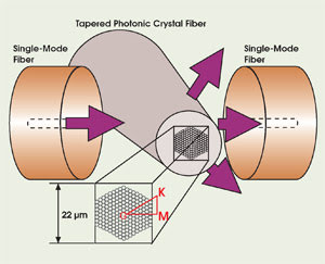
Figure 2. In the transverse probing of photonic crystal fiber, light is incident from the side of the fiber, so the microstructure acts as a conventional photonic crystal.
This geometry has a number of advantages: The fiber draw process produces holes with extremely low surface roughness, and by filling the airholes with temperature-dependent fluids, the structure is rendered highly tunable.
We have performed extensive measurements and simulations of many fibers with different diameters and crystal designs. Although the low-index contrast prevents complete bandgaps, the transmission is strongly suppressed along certain directions.
The structures are modeled with two RSoft tools: BandSolve and FullWave. Band structure calculations using the plane-wave expansion tool BandSolve correctly predict the locations of these partial gaps. The detailed transmission spectra of these structures are found using the finite difference time domain simulator FullWave.
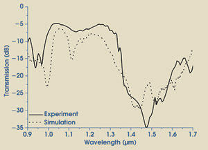
Figure 3. There is close agreement between the experimental and numerical finite difference time domain transmission spectra.
The close agreement between the simulated and measured transmission spectra (Figure 3) allows us to use transmission measurements and calculations as a sensitive probe of the preservation of the microstructure during tapering. This is further confirmed by direct electron microscope images of the fiber.
Acknowledgments
We thank our numerous collaborators in this work, including Robert Scarmozzino at RSoft Design Group Inc., and Paul Steinvurzel, Airlie Chapman, Boris Kuhlmey and Eric Mägi at the Centre for Ultrahigh-bandwidth Devices for Optical Systems at the University of Sydney.
Meet the authors
Michael J. Steel is a senior scientist at RSoft Design Group Inc. and an honorary associate at the Centre for Ultrahigh-bandwidth Devices for Optical Systems at the University of Sydney in Australia (e-mail: [email protected]).
Benjamin J. Eggleton (e-mail: [email protected]) is the director and Peter Domachuk and Hong Nguyen are graduate students at the center.