A multipart optical design for 3D laser triangulation delivers higher spatial resolution and faster acquisition speeds.
JOHN FILHABER, COGNEX CORP.
Quality assurance systems utilizing
3D machine vision technologies
can inspect products, detect defects, measure all dimensions of a part simultaneously, and locate randomly oriented items, among other tasks. For tasks requiring height, length, and width information, 3D vision offers advantages over 2D alternatives.
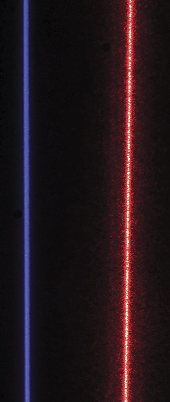
A blue, speckle-free laser and a red laser with speckle. The uniformity of the speckle-free line and the design of its associated optical elements leads to better accuracy, as well as resistance to occlusion and blocking for inverted installations. It also delivers more light to the target while being safer for human operators. Courtesy of Cognex Corp.
While several 3D imaging techniques exist, laser triangulation represents the fastest and most cost-effective method for in-line 3D quality inspection for packaging, assembly, and similar applications. One issue inherent in 3D laser triangulation, however, is the interference pattern that creates laser speckle — defined as the granularity of random bright and dark spots in the laser light. Laser speckle represents one of the main sources of measurement error in laser triangulation. This challenge has prompted interest in solutions that can either reduce or even eliminate the impact of laser speckle in 3D laser triangulation systems while increasing system speed and spatial resolution.
Leveraging lasers
Three essential elements comprise a 3D laser triangulation system: a laser line generator, a camera for capturing the laser line’s reflection, and a computer for processing the image and extracting 3D (and sometimes 2D) data. Today’s most advanced solutions combine all three of these elements into a pre-calibrated housing, simplifying installation and operation.
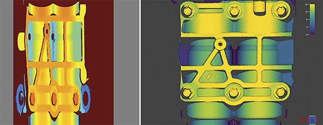
A 2D height map (left) and
a 3D point cloud (right).
Notice the difficulty in the
height map in determining
what is on top versus on
the bottom when color is
the only gauge for height
information. In the 3D point
cloud projection, true
volumes are displayed and
high points are highlighted
in light colors, just as they
would be in a real-world
scene. Courtesy of Cognex Corp.
When applying these systems to inspect items on a conveyor belt, for example, the system’s camera captures a series of profiles of each object as it crosses the laser line’s plane. The camera maps the object’s height by capturing how the laser line projects onto the object and reflects back. Image processing software assembles the individual profiles of reflected light into a 3D point cloud or surface map.
Laser light sources suit 3D scanners particularly well because their coherent beams represent the thinnest, brightest, and least divergent lines possible. When the laser is spread into a thin sheet of light, such as the fan-shaped beam of a laser profiler, it can project great distances with a thickness comparable to that of a few sheets of paper. Here is where laser speckle enters the conversation and presents issues.
A musical metaphor
To understand laser speckle, visualize a concert hall with two violinists and one audience member. The audience of one, sitting in the middle seat in the orchestra — equidistant from each violinist —
represents the 3D system’s image sensor.
One violinist plays a perfect A note at
440 Hz, and the other violinist plays the same note using the same force and friction. While the distance between the audience member and each violinist is equal, minute variations inherent to each violin will slightly affect how each note sounds.
The audience member hears the violins’ notes plus the sum of all the reflections from everything else in the room. Like the laser, the violinists play pure tones — steady sine waves of only one frequency. But the waves emanating from each violin take many paths to the audience member’s ears. This single frequency can combine the sine waves to either increase their collective intensity, or each will act to cancel the other out, creating moments of lower-intensity sound. A peak cancels a trough, for example.
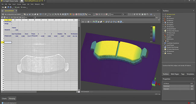
The In-Sight Vision Suite running inspection analysis on a brake pad clearly shows the planarity of the pad at key inspection points, leaving no doubt as to whether the pad material is raised above or below the supporting metal. Courtesy of Cognex Corp.
Furthermore, objects located behind the violinists, such as chairs and wall panels, reflect the sounds from various distances and cause different phases. As a consequence, the loudness or intensity of the sound that the audience member hears will differ based on small changes in the source location. The speckle effect is similar. Microscopic changes in the surface roughness of the object being scanned — similar to the onstage clutter in the concert hall example — cause sections of the laser light to appear brighter or darker to the camera.
In metrology applications that require a straight laser line on a flat part, speckle can create significant issues. The random dark and light areas in the beam create a wavy laser line, which can cause random height errors that calibration cannot fix. This fundamental limit of accuracy in any laser measurement system has plagued
in-line metrology systems for decades.
Mitigation and trade-offs
Speckle affects all 3D laser triangulation systems, and engineers have attempted to reduce its impact in various ways. Using certain wavelengths or adjusting camera aperture can control speckle to some extent because speckle contrast is proportional to wavelength and inversely proportional to aperture. Applying lasers that emit a shorter wavelength, or using cameras with a larger aperture, may lead to a 50% reduction in average speckle contrast, but the peak-to-valley error does not change much. After just one of these adjustments, if the speckled laser line were a road with potholes, the road may have fewer and shallower potholes, but several big potholes would still exist.
Acquiring multiple images and averaging them together is another method for combating speckle. Averaging multiple images reduces speckle contrast from the final image by the inverse of the square root of the number of images, provided the speckle patterns have been changed enough by an object’s motion through
the beam or by some other means. This technique produces an image that naturally averages spatial features. But the method, which involves significant amounts of time and processing overhead, is not suitable for many inspection
applications.
Two classic techniques used in laser holography also combat speckle by moving the laser, or by moving a diffuser placed between the laser and the scene being illuminated. While these solutions can reduce or nearly eliminate speckle, moving heavy objects — heavy in this case equating with a few grams — limits camera integration times to many milliseconds. This is problematic when many measurements require tens of microseconds of integration time. Furthermore, diffusers destroy beam quality, making a thin sheet of light impossible to achieve.
Lighting the path forward
An innovative new approach is enabling 3D laser profiling systems that can eliminate speckle and produce a clean, straight, and bright line. It employs a microelectromechanical system (MEMS) mirror to sweep a 450-nm blue laser beam back and forth at 28 kHz across a special diffuser optic. This microstructured optical element has the unique property of diffusing the laser light precisely in one direction, in a perfectly uniform fan, while preserving a sheet thickness equivalent to an undiffused laser beam. The configuration offers the robustness common to monolithic semiconductor beam-steering solutions. The full assembly, which operates well within Class 2M laser eye-safety limits, fits into a housing capable of operating reliably in dirty industrial environments.
The system owes its uniform intensity distribution and superb line quality to
the design of the microstructures in the diffuser and a field lens that concentrates the laser fan with very high efficiency
equal to traditional laser line generators. The diffuser and field lens generate a laser line on the object that, when scattered back to the image sensor, removes all speckle, without loss of light. Unlike other systems that attempt to reduce the
speckle and its effects by using violet lasers and large aperture cameras, the design of this system eliminates causes of speckle at the source, effectively eliminating both the shallow and the deep potholes common along the development path to a successful 3D laser scanning-based inspection system.
Furthermore, since the laser line projects from hundreds of different points along the multipart optic, it creates thousands of uncorrelated speckle patterns,
removing objective speckle. This projection method has the added benefit of being operator-safe. Since the laser line projects from a wide line source at the diffuser rather than being drawn by a
single point of light, the line brightness stays high while the amount of light that could pose a safety danger falls. (A wide source has much less light per square millimeter than a line drawn by an intense point of light.) As a result, the laser sources employed are classified at 2M rather than 3B or 3R, significantly reducing the amount of required safety equipment, engineering, and cost.
Another benefit of the laser projecting from thousands of points along the linear diffuser is that dirt and contaminants on the laser window will not break the projected line but will only dim it slightly, and not enough to negatively affect the 3D scanner’s operation.
The design generates the laser line from an overlay of hundreds of thousands of individual laser lines projected over the same area each second. This approach gives systems integrators more confidence when installing a 3D laser sensor in an inverted position because it reduces concerns that airborne contaminants settling on the laser window will quickly render their system ineffective.
Resolution and speed
With the multipart optical design, aiming the laser at a part or product during inspection generates a higher signal-to-noise value than conventional reduced-speckle 3D laser profiling solutions. This enables the system to run at high speeds, with individual frame acquisition times as low as 36 µs. Speckle-free laser lines also mean higher spatial resolution. With crisp, bright laser lines and fast acquisition speeds, high-resolution 2D grayscale and 3D volumetric images can be generated from the same solution, significantly expanding capabilities while reducing costs.
For many applications — such as those in the automotive assembly, packaging, and electronics industries — the question of 2D versus 3D imaging for machine vision has focused on the cost and complexity of 3D. Systems integrators and designers may prefer 3D height data over 2D data, however, when solving many automated manufacturing challenges. Advancements in 3D laser scanning are enabling lower image acquisition and
integration times, and lower operation costs, and they are freeing designers
from compromising on precision to reduce cost.
Meet the author
John Filhaber is director of optical engineering at Cognex Corp. He has over 30 years of
experience designing cutting-edge optical
systems for ground- and space-based
telescopes for science and defense, optical
switchgear for telecom, and metrology
equipment for semiconductor lithography, commercial aerospace, and factory automation markets; email: [email protected].