LED technology offers better color mixing and simplified thermal management for backlighting large LCD displays.
Thye-Linn Mok, Avago Technologies
Cold-cathode fluorescent lamps still are the industry standard for backlighting color LCD monitors and TVs, even though red, green and blue (RGB) LEDs have been demonstrated to bring benefits. When LEDs are combined with a color-management feedback controller, they can achieve a superior color gamut, more consistent brightness over time and temperature, and longer useful life than the lamps; they also can incorporate features such as a tunable white point. In addition, LED backlighting eliminates the traces of mercury found in cold-cathode fluorescent lamps, thus meeting mandates for the reduction of hazardous substances.
Out of the hundreds of millions of LCD panels produced every year, less than 1 percent are backlit with RGB LEDs. Many RGB LED solutions have been proposed to address this market, but so far none have had a thin enough profile while offering good color mixing, simple thermal management, plug-and-play installation and a cost that is competitive with that of fluorescent lamps.
Conventionally, LED chips have been mounted on substrates to create discrete LED components, which were attached to a printed circuit board. The solder reflow process typically used to attach the component to the circuit board subjects the LED chip to a substantial amount of heat that easily can damage the chip or degrade its performance. Hence, tight (and, therefore, expensive) process control is required for this type of assembly. In fact, the substrate cost is almost invariably the second-highest in an LED component, exceeded only by the cost of the chip itself.
A different approach, called chip-on-board packaging, seems capable of meeting all the requirements of backlighting. This method mounts the LED chip directly onto the printed circuit board using a conductive adhesive, which helps reduce costs by eliminating the substrate and complicated solder reflow assembly process. In addition, direct attachment can reduce the pitch between LED chips from the conventional 5 mm to approximately 2 mm and can lower the overall height of the light source (Figure 1).
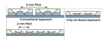
Figure 1. By mounting the LED directly onto the printed circuit board, a substrate is unnecessary, so pitch is reduced from 5 mm to approximately 2 mm.
Decreasing the LED pitch reduces the color-mixing area required (Figure 2), which means that the area of light loss is smaller. To achieve high coupling efficiency from the light source to the lightguide plate, a reflector is incorporated into the chip-on-board package to produce an oval radiation pattern. A narrow radiation pattern on the X-axis allows more light to enter the lightguide plate, whereas a wider radiation angle on the Y-axis enhances color mixing.
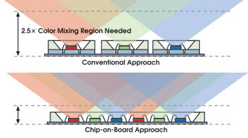
Figure 2. Reducing the pitch decreases the size of the color-mixing area.
Avago Technologies Ltd.’s current top-emitting chip-on-board assembly has a footprint of 100 × 18 × 3.6 mm, with an optical aperture of 96 × 6 mm, and the side-emitting package has dimensions of 100 × 18 × 8 mm, with an aperture of 96 × 4.6 mm. Other chip-on-board solutions do exist; however, using the chip-on-board LED in RGB backlighting is unique.
To investigate performance, top-emitting chip-on-board packages were retrofitted into the top and bottom edges of a cold-cathode fluorescent lamp backlight unit. Assembly does not require any special equipment: It simply is mounted by a screw, and the electrical connection is made through a plug-and-play eight-pin connector that mates with a standard female connector. The chip-on-board LED assembly fits into an existing fluorescent backlight unit without any major modifications.
The unit incorporates a lightguide plate with a reflector underneath and a diffuser and prism sheet on top. The light aperture is a long, rectangular strip extending to the edge of the lightguide plate, which means that light from the LED chips is channeled to the lightguide plate without much loss. The light from the RGB LEDs is mixed in the reflector cavity. The premixed white light can be observed just after it enters the lightguide plate.
The uniformity of the backlight unit was characterized with a nine-point measurement. The backlight unit demonstrates a brightness uniformity of more than 85 percent and a color uniformity (Δu'v') of less than 0.007 in CIE1976 LUV color space. The results are equivalent to the performance of a compact fluorescent light source.
Simple thermal management
A metal core printed circuit board is used in the package to provide a low thermal resistance, allowing heat generated by the LED chip to be transferred to the heat sink via the shortest possible thermal path (Figure 3), which increases the life span; moveover, the heat transfers more efficiently through three layers than through five. The chip-on-board packages are mounted directly onto the back metal (with thermal compound at the interface), so that the heat generated by the LED chips spreads efficiently on the large metal frame for efficient dissipation without additional heat sinking. In the demonstration configuration, the entire backlight unit can maintain a temperature below 60 °C.
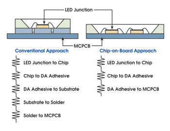
Figure 3. In comparison with the conventional approach, the thermal path is reduced. (DA = die attach, MCPCB = metal core printed circuit board.)
When compared with assemblies using conventional discrete LED packages, a chip-on-board approach can be compared with RGB LED-based LCD backlighting. The chip-on-board packaging has a thin outline, it produces better color mixing, and it requires simple thermal management and potentially lowers costs, all of which better match the requirements of customers. In addition, assembling a complete backlight using the chip-on-board package is similar to that using today’s fluorescent lamps, which makes a changeover relatively simple.
Meet the author
Thye-Linn Mok is a research and development project manager in the solid-state illumination division of Avago Technologies in Penang, Malaysia; e-mail: thye-linn.mok@avagotech.com.