Robert Schmitt, Björn Eric Damm,
[email protected], Susanne Nisch, WZL of RWTH Aachen University, Germany
Commercial image-processing systems employing standard components perform a variety of inspection tasks. When testing parts, only the function of the components – camera, illumination, computer and software – must be synchronized. Difficult inspection tasks, however, involve more complex component configurations that are beyond the scope of off-the-shelf solutions. Multiple design options do exist for these demanding tasks, but, because of the diversity of the components and algorithms, finding the optimal solution can be complicated, even for industrial image-processing experts.
A systematic four-phase approach facilitates the development of optimized image-processing solutions.The example shows the research method for identifying the best option for screw inspection.
In diverse sectors of industry, testing screws before assembly is vital for guaranteeing product quality. Various features of the screw must be inspected. For most applications, its functionality (thread, stability, etc.) is the critical property, but there are other important ones; for example, it is important that screws mounted in electronic devices be free of shavings or metal chippings, which can cause short circuits and often render expensive hardware defective.
At the Laboratory for Machine Tools and Production Engineering WZL of RWTH Aachen University in Germany, a team has initiated a project to detect chippings in the slots of screw heads for a company in the electrical industry. As part of this undertaking, the lab developed and demonstrated a systematic approach to finding the best inspection method.
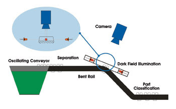
Shown is a system featuring a special bent rail and 0° dark-field illumination, which was systematically determined to be the optimal method for inspecting screw chippings.
The key testing requirements are determined by the customer’s cycle time in the production line, where the screws are transported to the assembly area through both oscillating and linear conveyors. Small screws, from M2 to M6 in size, have tiny chippings (250 × 250 × 100 μm), which is one reason the inspection system originally installed at the company did not meet its requirements. Another testing challenge is inspection rate, which must be 100 per cent. During one minute, about 200 screws are mounted, which equals a testing time of 300 ms per screw.
Developing the optimum concept
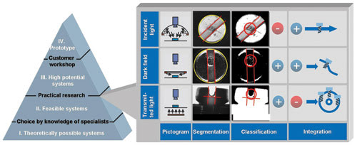
Development of the optimal testing solution can be divided into four phases. In the first, all options for the imaging system are investigated theoretically. The results usually can be categorized as either reasonable or virtually impossible. The second phase involves practical examination of the reasonable alternatives. In the third phase, the systems with the most potential will be presented to the customer and discussed. The results of the discussion are used for the fourth phase:, building the prototype.
For inspecting screws for chippings, various possibilities were investigated and classified. In particular, three illumination strategies were identified:
• Diffuse incident light
• A special technique utilizing dark-field illumination under a 0° angle
• Transmitted light
As part of the second phase, these three approaches were examined several times at a test stand. Algorithms had to be analyzed and the results included in the assessment. All algorithms were divided into the following logical steps: cognition of the screw/slot, segmentation of error, measurement of the features and, finally, classification of parts as good or defective. When analyzing the three illumination strategies, two key characteristics had to be considered: the quality of detection and the ease of method integration into the system.
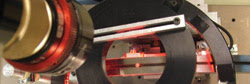
Pictured is a test stand for analyzing various illumination strategies and developing algorithms for the inspection of screw chippings.
As for quality of detection, the 0° dark-field illumination method turned out to be robust, and, because extraneous information was suppressed, it had high repeatability. On the other hand, the most stable algorithm was based on transmitted light. Positioning the screw head slots parallel to the direction of the light made it possible to detect the chippings with high accuracy. As for the diffuse incident light method, its results were not as good compared with those for the 0° dark-field and transmitted light methods. The technique was neither robust nor reliable in detecting chippings, so the diffuse incident light method was omitted.
When the remaining two techniques were considered from the perspective of systems integration, it was found that the transmitted light algorithm, which necessitated that every screw be aligned accurately, required great effort. A “roundabout”-type solution is possible for screw alignment, but the cost inflation is immense. The alternative algorithm, 0° dark-field illumination, required only that the screws be brought into the right position parallel to the dark field, a configuration that can be implemented relatively simply with a bent rail, so integration costs were lower than for the transmitted light system.
A multitude of factors
Because an image-processing system can comprise a multitude of components, defining an optimal system is a complex task. The example of testing chippings in screw heads demonstrates that a four-phase approach can home in on the optimal inspection system until a prototype can be defined. Another aspect of the solution is cost, which can strongly influence the application of measurement and testing technology, so price also must be optimized, also. In the example, the 0° dark-field illumination system is the optimum in terms of efficiency and cost. The calculated costs for a single prototype testing system are about 0.05 cents per screw. For 10 or more systems, the testing costs are reduced to 0.01 cents per screw. These figures include costs for integration into a production line, which are often are underestimated.