LEDs and geometrical optics principles combine to provide effective lighting profiles for microscopy, patterned projection, polymerase chain reaction, and other forms of analysis.
Ronian Siew and Li Hao Tan, Advanced Products Corporation
Even illumination patterns are of great importance when applied to biomedical imaging because they prevent lighting artifacts that could distort the picture of the sample being analyzed. Therefore, suppliers of microscopy solutions have made the integration and replication of these even patterns a priority in their commercial products1,2. With this goal in mind, any bright or dark features of a specimen on a microscope slide must be accurately reproduced for purposes of examination, whether by the human eye or by capturing the specimen’s image via a camera sensor contained within a digital microscope. Clarity is particularly important when analyzing conditions in cells, tissues, embryos, or other specimens for research or clinical diagnostics.
An image of an epithelial cell captured using top hat illumination.
Courtesy of Advanced Products Corporation Pte. Ltd.
Two common illumination techniques used in microscopy are known as critical illumination and Köhler illumination, and each has advantages and disadvantages. Other lighting techniques are also available for a variety of biophotonics applications. A new lighting method that uses lenses with LEDs to produce flat, top hat illumination has emerged, yielding even distribution of illumination across any plane of interest. This approach greatly benefits life scientists who examine dynamic and intricate samples.
Classical illumination techniques
To appreciate the nuances of how illumination problems can manifest themselves in biomedical imaging, it is important to understand what uniform or even illumination represents (Figure 1) in this context. In optical system design, the technical term used for describing illumination profiles is the irradiance distribution, which refers to the flux per unit area across the plane of illumination.

Figure 1. Global and local nonuniformity of an illumination profile across a plane. Courtesy of Advanced Products Corporation Pte. Ltd.
A dome-shaped irradiance distribution may be considered globally nonuniform across the sample, but it may be locally uniform in specific areas of the sample. And yet, globally uniform irradiance profiles can still have hot and cold spots — small regions of the illumination profile that have either excessive or insufficient brightness — which may be considered to be localized lighting artifacts in an image. These artifacts may arise from structural properties of the source, such as the coils of tungsten filaments, or even from wires and mechanical joints that run across LED surfaces.
Figure 2 illustrates the basic optical layout of five well-known classical techniques of illumination. For comparison, each system is depicted to project equal flux across equal illumination areas at a screen. Typically, the technique of critical illumination enables projecting a flat irradiance distribution, provided that the source is locally uniform. But sources often do not possess such uniformity.
For instance, if the source is a tungsten filament, then the image of the filament is projected onto the plane of illumination. If an LED is used, then wires and other electrical and mechanical structures that run across the emitter’s surface are projected to the illumination plane. Examples of images displaying these obstructions under a microscope, such as in fluorescence images of cells, are discussed in several technical white papers3.
In critical illumination, sometimes a simple defocus of the flux collector lens (or adding an engineered diffuser) is sufficient to homogenize the local nonuniformities, but this depends on the spatial dimensions and gaps between localized structures of the source. Köhler illumination — which is the most common technique used in bright-field and fluorescence microscopy — eliminates such localized nonuniformities. But if the source is small, such as an LED with a small emitter, then the result is often a globally nonuniform profile, even if edge vignetting is not present. However, in microscopy, other sources of nonuniform patterns in Köhler illumination can also appear in an image1.
Collimated illumination typically does not provide globally uniform irradiance distributions, due to the cosine fourth law as it applies to a lambertian LED source — that is, an LED whose datasheet indicates that its radiant intensity drops to roughly 50% of its peak at an output ray angle of 60° normal to the LED’s surface. This principle indicates that when such an LED is located at the back focal plane of a lens, the irradiance across a distant screen in front of the lens can take on a globally nonuniform profile. But if the LED is sufficiently large and locally uniform, then it is possible to produce a uniform illumination profile, provided that the plane of illumination is extended farther away.
This is known as the “searchlight” condition.
Finally, the last two techniques shown in Figure 2 can produce uniform irradiance distributions on a plane, but at the expense of using exotic components, such as fly’s eye arrays and light pipes, which can result in expanded system footprints and extended lengths or add to design complexity and cost.
For example, Tarou Ichimura and his colleagues have explored the use of fly’s eye lenses to produce uniform illumination at the specimen plane of a so-called trans-scale (multicellular) imaging microscope possessing a large field of view. But their system layout appears rather long4.
By distilling the effects of system length into a mathematical formula, it can be shown that a purely geometrical first-order equation governs the condition of equal flux projected onto equal areas of illumination for the critical and Köhler illumination techniques:
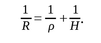 Here, R is the semidiameter of a projection lens (shown in the second system from the top in Figure 2), p is the semidiameter of the flux collector lens, and H is the radial height of the illumination profile measured from the optic axis. For a specified source size, flux collector size, and size of the illuminated area, this formula determines the size of the projection lens in Köhler illumination such that the total flux and size of the illumination area are the same in both the critical and Köhler techniques.
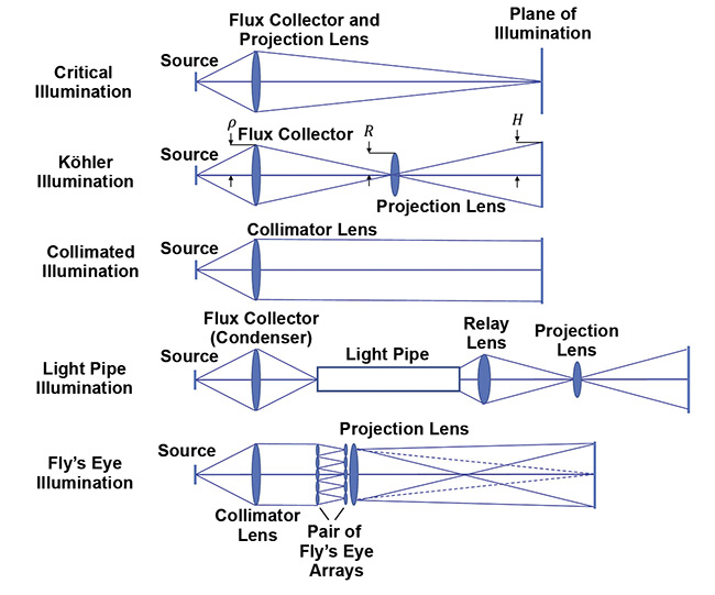
Figure 2. Five well-known classical techniques of illumination. Courtesy of Advanced Products Corporation Pte. Ltd.
Since the projection lens is conjugate to the source — that is, the projection lens’s plane is the location of the image of the source, which is formed by the flux collector — the formula also dictates the focal length of the flux collector for any choice of distance between the source and the flux collector. Finally, since the flux collector is conjugate to the area of illumination — that is, the plane of illumination is the location of the image of the flux collector, which is formed by the projection lens — this determines the system length.
In an epi-illumination microscope system that applies critical illumination, the objective lens serves as the projection lens. When applying Köhler illumination, an additional optical element called the field lens functions as the projection lens. This lens is mounted between the flux collector and the objective lens. No such formula like the one above applies to the collimated, light pipe, or fly’s eye techniques. Therefore, system length and size become free variables for these three approaches to produce uniform illumination. Systems designers and users usually pay a price for having a more complex setup because such a setup results in either a long (or wide) optical illumination subsystem due to the need to spread (or capture) rays and project them onto the illumination plane.
Enabling flat, even illumination
Ideally, a completely even illumination profile at a specimen plane would possess both global and local uniformity in its irradiance distribution. Such a distribution should therefore be flat across the area of illumination, with the exception of the sides, which are purposely clipped off to define the boundary of illumination. This profile may be called a top hat distribution. Figure 3 illustrates a new optical system design that projects a top hat distribution onto a distant plane, using a small green LED (1 × 1 mm) as the source. Experimental data for this optical design is shown in Figure 4. The specific features of the rays that propagate through the lens systems have been purposely hidden.
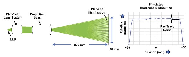
Figure 3. A flat, top hat irradiance distribution produced by an optical setup using a flat-field lens system, which homogenizes all of the rays within the field of view of illumination. Courtesy of Advanced Products Corporation Pte. Ltd.
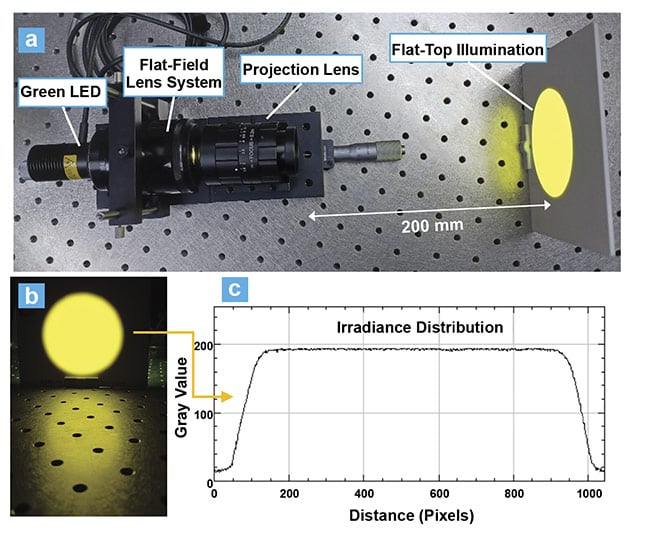
Figure 4. Experimental data shows the desired top hat irradiance distribution on a screen, based on the design shown in Figure 3, including the benchtop setup (a), the image of the distribution taken behind the screen (b), and the horizontal distribution (c). Courtesy of Advanced Products Corporation Pte. Ltd.
While the data shown in Figure 4 was obtained using a green LED, the technology is applicable to any color of LED emission and is, in fact, largely unchanged by chromatic aberrations, with the exception of lateral color aberration at the edges of the irradiance distribution. However, if the region of interest is smaller than the total illuminated area, then lateral color would be inconsequential. Also, no localized structural nonuniformities across the LED’s surface would be visible at the illumination plane. In particular, if a discrete array of emitters composes the total LED surface, the nonuniformities would be completely homogenized at the plane of illumination. To see why this is so, one need only observe in Figure 3 that the system comprises two parts: a projection lens and a lens system that provides flat-fielding effects. This is precisely equivalent to a Köhler system, which homogenizes local nonuniformities. Finally, if the projection lens’s intrinsic relative illumination is globally nonuniform, then a flat-field lens system can be designed to have adjustments that compensate for this nonuniformity, yielding a flat-top distribution across the field of view.
When the projection lens in Figure 4 is appropriately configured, it can serve as a coupler lens that enables flat-field rays to be focused into a microscope objective, enabling the production of a flat-top illumination distribution at a specimen plane (Figure 5).
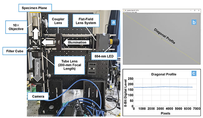
Figure 5. An autofluorescent blank slide viewed under 10× magnification using a benchtop fluorescence microscope at 554-nm LED excitation. The optical benchtop setup using the flat-field lens system from Figure 4 (a). The image of the slide captured by the camera, which has 5472 × 3648 pixels and 2.4-μm pixel size (b). The irradiance distribution across the diagonal length of the image, displaying a flat-top distribution. The slight bump near the center is due to stray light in the setup (c). Courtesy of Advanced Products Corporation Pte. Ltd.
Benefits and applications
The flat-field lens system shown in Figures 4 and 5 comprises Villuminator (or Venture Illuminator) modules, which are packaged subassemblies that can provide 20% to 50% flux collection efficiency from an LED. They can be made to project any desired shape and size of a flat-top illumination profile on a region of interest, such as the specimen plane of a fluorescence microscope system (Figure 6).
If such a microscope system is composed of a field lens for Köhler illumination, then replacing its flux collector with a flat-field module enables flat-top illumination at the specimen plane (Figure 6b). As can be seen, the image with top hat illumination displays the highest level of detail without edge darkening.
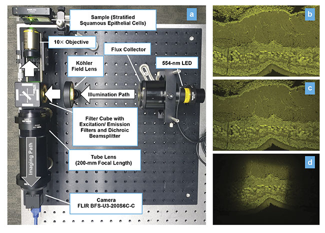
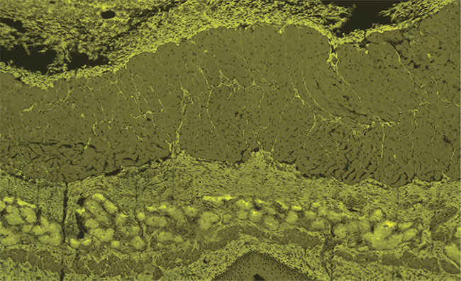
Figure 6. A fluorescent bio-sample of stratified epithelial cells viewed under 10× magnification in a benchtop fluorescence microscope at 554-nm LED excitation. The optical benchtop setup (a). An image of the sample captured with top hat illumination using a Villuminator flat-field module as the flux collector (b). The sample under Köhler illumination displays edge darkening (c). The sample under critical illumination as a consequence of projecting the LED’s square emitter onto the sample. Enlargement of the projected LED image is possible, but if the LED consisted of arrays of emitters then this would lead to local nonuniformity across the field of view (d). Courtesy of Advanced Products Corporation Pte. Ltd.
In fluorescence microscopy, a benefit of having top hat illumination is that digital flat fielding (in which lighting artifacts are corrected by software) would no longer be required, thereby permitting optimal use of computer memory for other computational tasks, such as image thresholding, segmenting, contrast enhancement, and analysis of a region of interest in the sample. Also, having top hat illumination allows the ability to rule out any contributions from the source and optics to the presence of artifacts identified in the image of the region of interest.
Biophotonics applications that use spatial light modulators for patterned projection, such as photostimulation or cellular imaging, may also benefit from having top hat illumination. For example, when the surfaces of liquid crystal displays and liquid-crystal-on-silicon chips are illuminated with top hat illumination, their patterned projections would possess very even distributions. In superresolution microscopy5 and optogenetics6, spatial light modulators that require oblique illumination — such as digital micromirror devices — would benefit from applying an oblique illumination version of a flat-field lens module (Figure 7). This is because such methods depend heavily on the activation of a specific number of fluorophores, and any artifacts are detrimental to the excitation of the fluorophores or to the collection of information from the image generated.
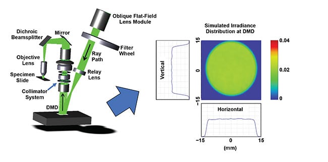
Figure 7. The optical concept layout for a digital micromirror device (DMD)-based system that incorporates top hat illumination to create patterned projections in superresolution microscopy and optogenetics. The concept is based on an oblique version of the module from Figure 4. Simulated irradiance is shown using the Zemax OpticStudio optical design program. Courtesy of Advanced Products Corporation Pte. Ltd.
Further, the technology that has been applied to develop such flat-field modules can be made portable for use in field applications. In forensics, a hand-held module can provide uniform ultraviolet illumination onto fluorescent samples for detective work to capture all relevant detail from the samples. The technology could also benefit other applications, such as uniform disinfection by UV irradiation. Uniform irradiation can normalize the results of the irradiation. In real-time polymerase chain reaction (PCR) and digital PCR applications, uniform illumination provides equal excitation of fluorophore-labeled DNA samples dispersed across microtiter plate wells and microarray partitions, which in turn yields uniform detected fluorescent signals7.
Top hat illumination using LEDs
Optical designers and engineers who are involved in laser beam shaping would know that top hat irradiance profiles can be generated using a laser beam shined through a pair of aspheric collimating lenses. Moreover, when the light source is a laser, engineered diffusers and diffractive optical elements are also well suited to the task. Therefore, lasers and laser beam-shaping optics would appear to be integral to the future development of top hat illumination, particularly for biomedical imaging. However, lasers can be expensive, and their highly coherent beams produce speckle artifacts unless a de-speckling technique is used. In contrast, incoherent sources such as LEDs are cost-effective and produce no speckle. This fact is well noted by bioimaging researchers, who have explored switching to LEDs for illumination in confocal microscopy.
However, using LEDs to generate top hat irradiance distributions can be challenging. Unlike lasers, LEDs are subject to the spreading of flux across optical component surfaces and illumination planes. It is this spreading effect that causes a nonuniform global irradiance distribution that is unsuitable for cellular imaging, for example. Under the condition of having a fixed source size and angular spread of the rays collected by illumination optics (which is a condition defined solely by the properties of the selected light source for illumination), it becomes impossible to have zero spread of the rays unless they are made to occupy an infinitely large space as they travel toward the plane of illumination. Fortunately, special optical modules can be assembled that project flat-top irradiance distributions across a plane, even if the plane is tilted (or if the module is illuminating a plane at an oblique angle).
These special optical modules should satisfy the needs of researchers, and potentially clinicians, who desire uniform illumination in bio-imaging, especially if the irradiance is completely flat across any specimen plane. What’s more, as has recently been demonstrated, this can be accomplished using LEDs, which are today’s industry standard for virtually any lighting application. In biomedical imaging and detection, the benefits are quite evident because the desire for enhanced resolution is dovetailing with the need for uniform illumination to capture every relevant detail and make this detail readily apparent under the microscope.
Meet the authors
Ronian Siew is an optics consultant at Advanced Products Corp. Pte. Ltd. (a subsidiary of Venture Corp. Ltd.). He also serves as an associate editor in the area of optical design for SPIE’s Spotlight book series; email: [email protected].
Lihao Tan, Ph.D., is a senior optical system engineer at Advanced Products Corp. Pte. Ltd. (a subsidiary of Venture Corp. Ltd.) His works have involved the development of illumination systems using lasers and LEDs for life science applications; email: [email protected].
Acknowledgments
The authors are grateful to their colleagues Qiwen Peng, Xiaoting Huang, Ziv Lim Peng Huay, and Lianyew Gan for their support. They also thank Venture leadership — Minglee Tay, Simon Tan, Eric Chuah Yuan Chang, and Weehan Kuek — for their encouragement and support.
References
1. Zeiss. Education in microscopy and digital imaging, https://zeiss-campus.magnet.fsu.edu/articles/lightsources/lightsourcefundamentals.html.
2. Olympus. Microscope illumination, www.olympus-lifescience.com/en/microscope-resource/primer/anatomy/illumination.
3. Applied Scientific Instrumentation. Epi-illumination options and laser coupling, https://asiimaging.com/docs/epi_illumination_options?s[]=kohler#epi-illumination_options_and_laser_coupling.
4. T. Ichimura et al. (2021). Exploring rare cellular activity in more than one million cells by a transscale scope. Sci Rep, Vol. 11, No. 16539, www.doi.org/10.1038/s41598-021-95930-7.
5. D. Dan et al. (2013). DMD-based LED-illumination super-resolution and optical sectioning microscopy. Sci Rep, Vol. 3,
No. 1116, www.doi.org/10.1038/srep01116.
6. J. Allen (2017). Application of patterned illumination using a DMD for optogenetic control of signaling. Nat Methods, Vol. 14, No. 1114, www.doi.org/10.1038/nmeth.f.402.
7. R. Siew et al. (2021). Optical system, and method for illuminating a sample plane. U.S. Patent Application No. 20210140885, https://patents.google.com/patent/US20210140885A1/en?q=20210140885.