Threshold Testing of Thin-Film Optics Automated inspection can help detect laser damage.
Alan Streater and Trey Turner, Research Electro-Optics Inc.
The demand for high-energy laser systems has increased steadily in recent years, driven by applications in defense, semiconductor processing and basic research, among others. The systems range from those that are continuous wave (CW) to those with femtosecond pulses and that have wavelengths from the ultraviolet to the mid-infrared. However, in many cases the weak link in the system is the thin-film coatings that comprise the mirrors and antireflection surfaces within the laser cavity or along the beam path.
Optical components have various damage mechanisms and performance for some regimes of laser operation. For example, thin-film coatings designed for optimal damage resistance under short-pulse conditions are not the same as those designed for optimal CW performance.
Pulse duration, repetition rate and operating wavelengths are critical factors that must be considered when specifying the damage threshold of any optical component or thin-film coating. Damage-testing protocols are generally specific to certain combinations of these factors, and testing methodologies are changing as technology develops and new applications emerge.
One such change is the advent of automated inspection technology. Using these instruments to sense damage events can eliminate the human element from detection and measurement.
Laser damage testing
Laser damage is a general term for any irreversible effect to an optical component caused by exposure to laser radiation, making the optic unusable for its intended application. The effects can take the form of increased scatter or absorption, changes in transmission or reflection performance, increased wavefront error, or physical damage such as cracks and pits. The mechanisms that can cause these effects are myriad and include absorbing defects within the bulk or thin-film coatings, compaction of materials leading to changes in optical properties of bulk or thin-film materials, dielectric breakdown of bulk or thin-film materials, stress fractures induced by large thermal gradients or by differences in thermal properties of the materials, and several others that have been identified by previous work.1,2,3,4
Unfortunately, the most common damage mechanisms (defect induced) are statistical in nature and typically sparse. This means that a large number of sites on a given component must be tested, and that the sites of defects (typically coatings) must constantly be monitored to screen for failures and to correct process variations. The reliable and efficient testing of the laser damage threshold of optical coatings and components is thus critical for manufacturers hoping to deliver components and systems for today’s cutting-edge laser applications.
The protocols used to test optics for these defects often are specified by the user, and many institutions and corporations have created their own internal testing methods. A commonly referenced protocol for short-pulse, single-shot applications was developed and is maintained by Lawrence Livermore National Laboratory in California in support of its National Ignition Facility (NIF).5 The only existing international standards describing laser-damage testing are included in the ISO 11254 series.6,7,8 Each of these protocols applies to a relatively narrow range of applications.
Any methodology to test the laser damage threshold of an optical component must be designed to match the intended application environment as closely as is practical because the mechanism of damage can vary tremendously, depending on the parameters of the use environment. The exposure wavelength, pulse duration and repetition rate are especially important factors. There are limited regions where the damage threshold is roughly proportional to wavelength9 and even more limited regions where the damage threshold depends weakly on pulse duration5, but, otherwise, these factors cannot be reliably scaled according to existing models of laser damage.
Laser damage testing traditionally has relied on human inspection for classifying and counting damage events. The typical test setup involves an exposure laser and an operator who watches for damage, usually with the help of a magnifying video system. Damage is indicated when the operator observes a permanent change in the surface. This method is highly sensitive to the skill and training of individual operators and provides little quantitative feedback. It is generally considered unsuitable for testing by today’s standards.
An improvement on this technique has been to add a laser-scatter measurement as a detection tool. In this configuration, a low-power CW laser (typically a red HeNe) is directed at the sample site, and light scattered from the site is collected onto a photodetector. The scatter signal is recorded both before and after exposure to the high-power laser radiation, and the difference should represent the amount of damage. This approach reduces the influence of operator judgment, is less sensitive to contamination and pre-existing defects and provides quantitative information as to the size of the damage. Because the scatter signal level depends strongly on the shape of the defect, it does not correlate well to the size of the damage occurrence.
Recent advances
In support of production of high-damage-threshold optics for NIF, Research Electro-Optics Inc. (REO) has developed a system that uses automated inspection technology to detect and measure laser damage events (Figure 1).10 This removes the human element from the detection of laser damage. The system also provides a wealth of information not previously available, such as size histograms of damage events and maps showing both sizes and spatial distributions of damage events over a large area.
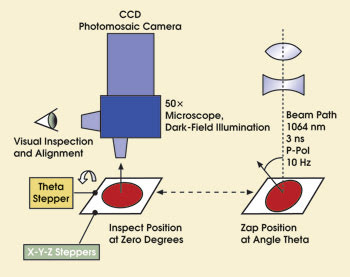
Figure 1. The automated laser damage testing system uses a CCD camera to record images of damage events on a test sample.
This information can be extremely useful in process control. For example, damage events that are spatially clustered into streaked regions can be attributed to improper cleaning of the substrate before thin-film coating. The automated system has proved sensitive and stable over time, and a similar system was recently developed and demonstrated by scientists at Lawrence Livermore in support of the NIF.11
REO’s automated laser damage threshold testing system uses a camera attached to a microscope to take digital photos before and after laser exposure. The digital images are analyzed with an automatic inspection algorithm that identifies defects as clusters of white pixels. The defects on the “before” and “after” photos are compared. If there are new defects or if existing defects are found to have grown, the sizes and locations are recorded.
For testing under the NIF protocol, the system uses a grid of 49 microscope photos to cover a 1 × 1-cm2 testing area. Figure 2 shows an example of laser-induced damage sites over this large testing area. The sizes of the circles indicate the sizes (greatly magnified) of damage events. Blue indicates a new site and red, the growth of an existing defect. This test is normally repeated at successively higher fluences.
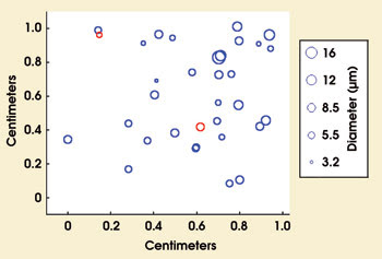
Figure 2. This spatial map of laser damage events on a 1 × 1-cm area is typical of measurements made with the automated damage-testing system. Circle diameters indicate size of damage growth (see key). Blue indicates a new event and red, an existing defect that grew in size.
The laser damage events also can be classified into size groups and graphed as histograms. For moderate fluences (up to about 20 J/cm2) the smaller damage sites normally do not grow upon subsequent exposure. To verify this, the system can return to sites where small damage occurred so as to perform growth testing. The damage threshold is calculated by counting all damage events beyond a specified size.
This size threshold is more quantitative and flexible than a threshold based on detectability for a specified system. The number of damage events is then plotted as a function of fluence, forming a damage-event curve. Damage-event curves from several tests are shown in Figure 3. The threshold is sometimes defined by fitting a straight line through the points beyond where zero events occur and finding the intercept. The NIF protocol calls for a more conservative threshold by simply defining the damage threshold as the highest fluence where no events in the specified size bin occur.
Optics can be tested up to the specified fluence, or tested to failure, which reveals how much of a cushion there is between the spec and true failure. Tests to failure are normally done on witness pieces, which are fabricated in the same manner as the part substrates, and are coated alongside the actual parts. It is wise to occasionally test real parts to failure to assure that the damage event curves are similar for real parts and witness parts.
Figure 3 shows damage-event curves from several coating runs, including two failed ones. Such tests are used as process controls, and steps are taken if performance drops below a specified level (to the left of the broken line in Figure 3).
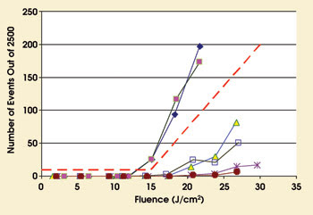
Figure 3. These data plots show the number of damage events above a certain threshold (10-μm diameter) that occurred during 2500 exposures at each laser fluence, for six different samples. The red broken line specifies the minimum acceptable performance. Four of the samples met the performance specification, and two failed.
In 38 runs between April 2005 and May 2006 of antireflection coatings for parts with a 12 J/cm2 damage threshold specification, there have been two failed runs, both early in the production cycle. Subsequently, 35 consecutive runs all passed this relatively high damage threshold specification. (Damage thresholds for high reflectors, partial reflectors and polarizers are generally higher.)
Future directions
The evolution in testing methods for laser damage is heading toward techniques that allow more precise and detailed characterization of the detected damage, including studying the appearance of a damage area in three dimensions and the time evolution of the damage. Additional measurements such as localized temperature and stress profiles are being demonstrated.1 This information is expected to yield insight into the fundamental mechanisms of laser damage.
Application of today’s technology into the deep UV and IR wavelengths as well as to shorter pulse duration also is anticipated. As CW laser systems achieve energy densities that challenge today’s coating technologies, we also expect the application of similar methodologies to testing optics for CW laser damage.
Meet the authors
Trey Turner is vice president of business development at Research Electro-Optics Inc. in Boulder, Colo.; e-mail: [email protected].
Alan Streater is an R&D scientist at Research Electro-Optics; e-mail: [email protected].
References
1. For a broad range of high-level articles on laser damage testing, please see the proceedings of the Annual Boulder Damage Symposium, published by SPIE. For example: Proc SPIE (2005), Vol. 5991, and Proc SPIE (2006), Vol. 6403 (to be published).
2. M.D. Feit and A.M. Rubenchik (2004). Implication of nanoabsorber initiators for damage probability curves, pulse length scaling and laser conditioning. Proc SPIE, Vol. 5273, p. 74.
3. A.M. Rubenchik and M.D. Feit (2001). Annual symposium on optical materials for high-power lasers. Boulder, Colo.
4. M.D. Feit and A. Rubenchik (June 2004). Influence of subsurface cracks on laser induced surface damage. 2003 Proc SPIE, Vol. 5273, Gregory J. Exarhos et al, eds,, pp. 264-272.
5. NIF procedure MEL01-013-OD. Small optics laser damage test procedure, revision OD. NIF pdf version of ECMS CM release 20050620 13:56 5008633 OD, National Ignition Facility (June 20, 2005).
6. ISO 11254-1:2000 (2001). Lasers and laser-related equipment: Determination of laser-induced damage threshold of optical surfaces, Part 1: 1-on-1 test. ISO copyright office, Geneva, www.iso.ch.
7. ISO 11254-2:2001 (2001). Lasers and laser-related equipment: Determination of laser-induced damage threshold of optical surfaces, Part 2: S-on-1 test. ISO copyright office, Geneva, www.iso.ch.
8. ISO 11254-3:2006 (2006). Lasers and laser-related equipment: Determination of laser-induced damage threshold of optical surfaces, Part 3: Assurance of laser power handling capabilities. ISO copyright office, Geneva, www.iso.ch.
9. C.W. Carr et al (2003). Experimental study of wavelength dependent damage threshold in DKDP. Proc SPIE, Vol. 4932, p. 385.
10. D.C. Ness and A.D. Streater (2005). Automated system for laser damage testing of coated optics. Proc SPIE, Vol. 5991, p. 59912B.
11. J.E. Wolfe and S. Schrauth (September 2006). Poster presentation at the Boulder Damage Symposium XXXVIII: Automated laser–damage test system with real-time event imaging and detection. SPIE 6403-88.