Full company details
Chroma Technology Corp.
 10 Imtec Lane
Bellows Falls, VT 05101
United States
Phone: +1 802-428-2500
Fax: +1 802-428-2525
Toll-free: +1 800-824-7662
Sputter-Coated Optics Improve Machine Vision and Remote Sensing
Photonics Spectra
Sep 2022Sputter-coated thin-film interference filters transmit more of the desirable light and block more of the noise to improve imaging system speed, contrast, and cost.JOHN ATKINSON, CHROMA TECHNOLOGY CORP.
For biomedical instrumentation applications such as fluorescence microscopy and Raman spectroscopy, sputter-coated thin-film interference filters deliver exemplary performance. These filters also enhance imaging system performance for applications such as remote sensing and industrial automation. Filters for wavelengths from the ultraviolet (UV) to the shortwave infrared (SWIR) boost contrast, enabling an imaging system to acquire more information faster and at lower overall system cost.
Magnetron sputtering creates customized thin-film interference filters with high durability and the spectral precision needed to transmit desired light while blocking ambient light that contributes
to noise. High-quality optical filters
with consistent center wavelength accuracy improve imaging system contrast, which enables the system to differentiate between features. The resulting high
contrast and high signal-to-noise ratio (SNR) are particularly crucial for remote sensing and machine vision applications such as multispectral imaging and barcode reading.
Defining the important wavelengths
Optical filters accurately and reliably transmit or block light over a specified band of wavelengths — the wavelengths that correlate most closely with the characteristic of interest. Optical filters are therefore critical in making remote sensing and machine vision systems relevant and cost-effective for a variety of tasks.
An optical filter limits the transmission of light to a specified spectral range of interest, reducing transmission at wavelengths outside this range to almost nothing.
For example, a filter with an optical density of 6 transmits only one-millionth of the incident light at a given wavelength. In this way, optical filters play a small but crucial role in defining sensor performance, and optimizing them is
an important aspect of system design.
Thin-film interference filters are produced by depositing coatings, made up
of multiple dielectric layers, on a glass substrate. The differing refractive indices of the materials in the thin-film layer stack, and the extremely precise tuning
of each layer thickness — which can range from just a few nanometers up to several microns — creates the conditions for optical interference (Figure 1).
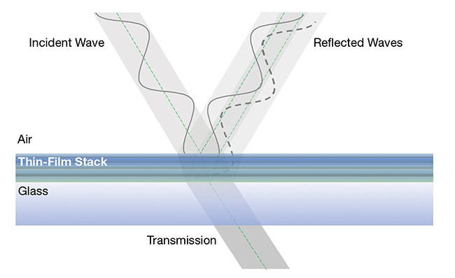
Figure 1. Thin-film multilayer stacks use constructive interference of the reflected waves occurring at the multiple interfaces to block unwanted light. The layers can be highly optimized for precise spectral discrimination. Courtesy of Chroma Technology.
Interference is the mechanism by which light of different wavelengths can either be transmitted or reflected. By optimizing the coating layer by layer, it is possible to achieve a precisely defined bandpass with very high transmission at wavelengths of interest in combination with very high
reflection — that is, very low transmission or high optical density — across other wavelengths.
Interference coatings made with sputtering deposition techniques are the technology of choice for optical filtration in remote sensing and machine vision
applications because of their durability and high spectral performance.
Reactive magnetron sputtering, for example, is a plasma-based, state-of-the-art coating deposition process used to make thin-film interference filters for fluorescence microscopy, Raman spectroscopy, lidar, remote sensing, and machine vision applications.
Sputter coating, like electron beam or thermal evaporative (“soft”) coating, is a form of physical vapor deposition that occurs under high vacuum.
During the process, a negative high voltage is applied to the metal (or semiconductor) target, creating a plasma of highly energetic ions (typically ionized argon gas) that are accelerated toward the target to release (or “sputter”) atoms from that target (Figure 2). In magnetron sputtering, magnetic fields help contain the plasma to increase energy and efficiency.
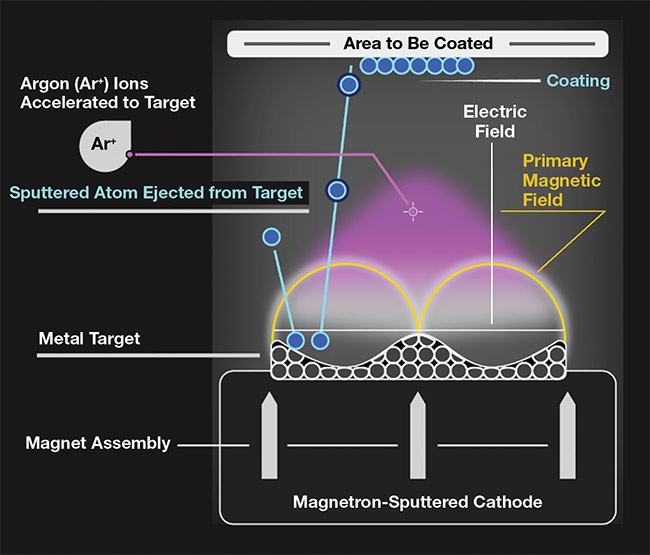
Figure 2. Magnetron sputtering equipment
applies a negative high voltage to a metal target and accelerates ionized argon (Ar+) gas plasma toward the target to dislodge metal material, which rises to coat the filter surface. A magnetic field contains the plasma to increase efficiency. The high energy of the sputtered material produces a much denser coating than the electron beam or thermal evaporation processes can deliver. Courtesy of Chroma Technology.
The sputtered atoms react with introduced gas — such as oxygen or nitrogen — at a substrate surface to form, in the example case, an oxide or nitride film.
An additional ion-assist process delivers energy to the growing film to promote void-free growth and a much denser coating, as compared with electron beam or thermal evaporation processes. Increasing
coating density reduces moisture penetration and the risk of damage or scratches. Oxide films are particularly durable and suitable for optical filters for the UV, visible, and SWIR wavelength ranges.
Reactive magnetron sputtering is a highly controlled process that, with
appropriate monitoring, enables design optimization and highly repeatable production of optical filters to extremely tight tolerances. The process not only ensures spectral precision but also enables precision manufacturing of complex
dual-band and even quad-band filter designs for multispectral imaging applications. Bandpass filters with specific
transmitting and blocking wavelengths can be highly tuned to subnanometer
accuracy, if required. Magnetron-sputtered filters are characterized by high thermal stability with minimal temperature-related wavelength shift (<0.005%/°C); high durability to extend lifetime; sharp, steep band edges; and consistent coating uniformity across the surface of a filter.
Sputtering can also be used to make longpass and shortpass filters, metal or dielectric mirrors, dichroics, beamsplitters, neutral-density filters, coatings for ultrafast-pulse lasers, and coatings for polarization control.
Remote sensing
Remote sensing technology allows mapping, classification, and investigation of Earth’s surface — land and water — in ever greater detail, and its use is increasing rapidly. The global market for remote sensing technology, valued at $12.4 billion in 2019, is expected to experience a compound annual growth rate of 11.6% over the forecasting period from 2020 to 2027
1.
Passive remote sensing, which relies on the sun for illumination, accounts for more than half of this market. Although agriculture drives much of the growth in passive remote sensing, other key sectors
investing heavily in the technology include Earth monitoring, defense, and civil security. Remote sensing is used routinely to map land occupation and use, to manage disasters (detecting and assessing pipeline leaks, for example), and to study coastal issues such as marine pollution and degradation. The technology is also used to study and monitor forest health. For instance, to help prevent wildfires, remote sensing can determine the fuel moisture by using data correlated to Fire Weather Index codes
2.
The use of solar radiation (instead
of a laser light source, for example)
differentiates passive remote sensing from active remote sensing techniques such as lidar and has important implications with respect to sensor engineering.
Optical filters are critical for enabling cost-effective passive remote sensing technology.
Earth’s atmosphere modulates the transmittance of solar radiation, but at Earth’s surface, appreciable energy levels are observed from 250 to 3000 nm (Figure 3).
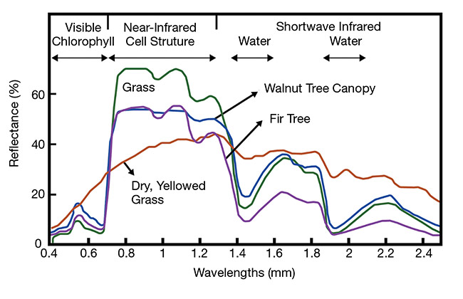
Figure 3. Materials absorb and reflect solar radiation to varying degrees at different wavelengths, creating identifying spectral reflectance signatures. Remote sensing systems need optimized optical filters to extract specific wavebands for analysis. Courtesy of Chroma Technology.
Precision agriculture
Passive remote sensing using multispectral imaging enables precision agriculture by accurately quantifying many crop health indicators. For example, the widely used normalized difference vegetation index evaluates biomass — critical for assessing global food supply — by measuring the reflected solar radiation of two bands, one red and the other near-infrared. Many other bands of interest from the UV to the SWIR are useful for estimating crop parameters such as leaf area, soil cover, water and nitrogen content, and chlorophyll concentration.
Multispectral imaging involves capturing multiple images, each of a particular band. An extreme example is hyperspectral imaging, which measures across hundreds or thousands of contiguous bands. For most commercial applications, detection over just a few appropriate bands is sufficient. This approach enables faster, more efficient measurement.
Hyperspectral imaging systems may therefore bring value in research and innovation when a wide spectrum is of interest or when specific wavelengths of interest have yet to be identified. The more typical challenge is engineering
a multispectral imaging system that
accurately, precisely, and reliably detects light at three to six carefully targeted wavelengths. Unmanned aerial vehicles or drones, for example, can carry multiple cameras, each with a filter, enabling adequate data acquisition with much lower cost and weight as compared with a hyperspectral camera.
The aim is to achieve high spectral resolution at certain defined wavelengths in the most cost-effective way. Many sensor configurations can achieve multispectral detection, but optical filtration helps all of them gather light at a wavelength or range of interest while minimizing noise from other spectral bands.
Automation and machine vision
Multiple components — including
lighting, lenses, camera sensors, and filters — can alter the performance of an industrial machine vision system. One way to measure performance is through contrast and resolution. Advanced filters improve machine vision by increasing contrast.
The term “modulation” refers to the parameter that people typically think of as contrast in an image. One way to measure how well contrast is preserved or transferred from an object to an image is by using a function of spatial frequency called the modulation transfer function (MTF). The MTF can measure the practical limits of resolution in an imaging system.
Resolution is the smallest distance
between two objects that an imaging system can reliably detect. For example, in Figure 4, the difficulty of determining whether the lines are joined or separate increases as the distance between lines decreases. Compare this with an eye exam, where it becomes increasingly
difficult to differentiate between letters
as they become smaller and closer together. An imaging system that cannot differentiate objects of interest will perform poorly.
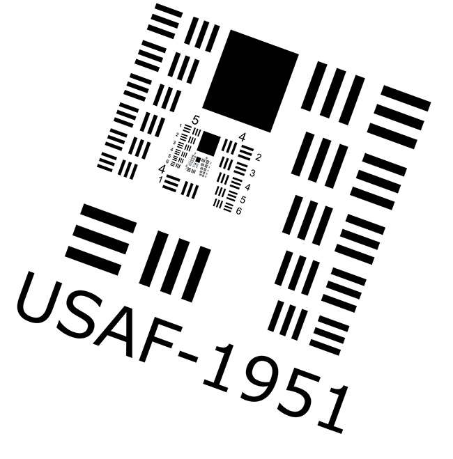
Figure 4. As frequency increases on the test target, it becomes harder for the optical system to efficiently transfer contrast, which lowers the modulation transfer function (MTF). Courtesy of Chroma Technology.
As line spacing decreases (that is, as the spatial frequency increases) on the
test target in Figure 4, it becomes increasingly difficult for the optical system to efficiently transfer contrast, which lowers the MTF. Improving MTF for the higher spatial frequencies is especially important for applications such as labeling and barcode reading.
Barcodes can become damaged, smudged, and dirty, challenging imaging systems. A system trying to read tightly packed barcodes on high-speed conveyors at various heights and orientations must maximize modulation. Noise (light pollution) from the sun or from lights outside the application can further reduce contrast and influence MTF, resulting in no-reads or misreads.
Enhancing contrast and MTF
Optical filters help preserve the resolution of an imaging system by enhancing
contrast and recovering the MTF performance lost when detecting objects illuminated with a broad spectrum of light. Filters block out-of-band light while transmitting the desired spectrum, dramatically improving MTF. The greatest gains come from choosing shorter wavelengths. The shorter the wavelength, the better the resolution.
Traditional colored glass filters made
of absorption glass can help improve MTF, but for high-precision applications,
interference filters provide a better passband shape. The passband shape for a traditional colored glass filter is Gaussian (Figure 5). The shape extends beyond the desired red spectrum, reducing contrast and degrading the MTF.
The interference filter’s square passband may bring to mind the myth that Gaussian-shaped passbands are better than square ones. If a filter’s passband extends beyond the bandwidth of the light source, the filter transmits more unwanted light. The goal is to maintain the greatest ratio of wanted to unwanted light. By passing more unwanted light, the Gaussian passband contributes to deteriorating MTF.
To prove the difference between the square and Gaussian passband, the equation on page 49 uses the area under each curve generated by the filters shown in Figure 5 to calculate the SNR. One decision will change the results: whether
ambient light within the desired bandwidth is added to the signal side or the noise side of the equation.
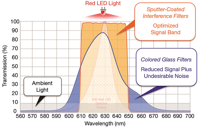
Figure 5. The passband shape of the interference coated filter helps the imaging system achieve reduced contrast and MTF, as compared to systems using traditional filters. Courtesy of Chroma Technology.
 The area under each curve generated by the filters shown in Figure 5 is used to calculate the signal-to-noise ratio.
If ambient light is considered noise, the SNR is 63.3 for the interference filter and 52.6 for the colored glass filter, a 20%
improvement. If ambient light is considered acceptable or is added to the signal side of the equation — resulting in an SNR of 134 for the colored glass filter and 3426 for the interference filter — the difference becomes 2500%.
These results show the potential performance boost of using interference filters, why they are valuable in many applications today, and why they will become increasingly important as machine vision advances. Greater contrast as represented by the MTF can increase production speeds and lead to more accurate inspections while reducing errors in manufacturing, inspection, warehousing, and logistics applications.
Bandpass filter as blocking filter
A filter’s main function is to block out-of-band wavelengths. If there is no blocking, there is no filtration, just transmission. The shaded areas in Figure 6 show the same transmission and passband plots from Figure 5. The unshaded area represents optical density.
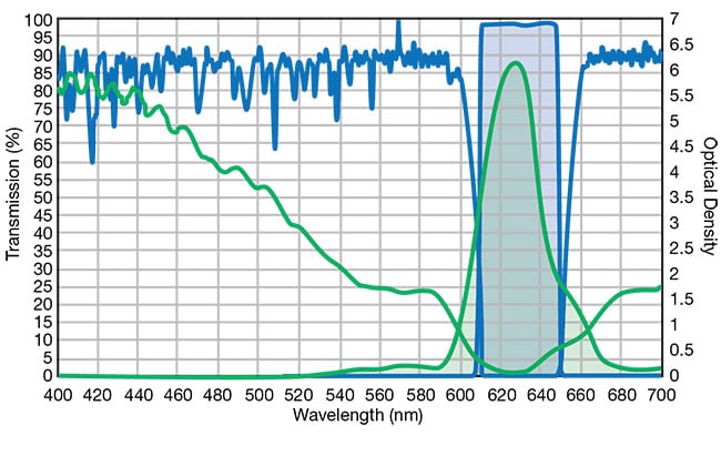
Figure 6. The plot of transmission and optical density (OD) for an optimized interference filter (blue) and a typical colored glass filter (green). The shaded areas represent the passband in transmission; the unshaded areas represent OD. The interference filter transmits up to 15% more desirable light, which increases throughput. Its steeper edges also improve spectral precision, and its higher blocking levels (OD) increase the SNR and contrast.
Courtesy of Chroma Technology.
The lower optical density of the green curve in Figure 6 indicates where noise is introduced to the image, diminishing the SNR. The interference filter’s optical density, represented by the blue curve, blocks much more of the out-of-band spectrum, transmitting only the targeted bandwidth.
Some vision system designers consider filters with optical density ≥4 to be unnecessary because they add cost without improving performance.
However, if very bright, unwanted light sources (for example, lasers) are present in the imaging scene, the sources must be blocked, and an optical density of three may not provide enough attenuation.
Interference filters designed with high angle tolerance naturally deliver high optical density without extra coating
layers or cost.
Facilitating modern imaging needs
Even the simplest of warehouse and industrial applications are expanding to higher throughputs, wider object variety, and lower tolerance for misruns and read errors. These factors increase the relevance of sputter-coated thin-film interference filters in imaging system design, to optimize the signal to noise, contrast, and the modulation transfer function for a specific application.
As more complex machine vision
applications are deployed, customized interference filters will help designers manage the complicated illumination
issues that currently limit widespread multispectral applications for food inspection, plastic sorting, and robotic guidance.
Meet the author
John Atkinson is principal product engineer
at Chroma Technology Corp. He has a bachelor’s degree in physics, and he received a master’s degree in photonics from Boston University. Atkinson has experience in optics, imaging, displays, astrophysics, and optoelectronics; email:
[email protected].
References
1. Grand View Research (September 2020).
Remote sensing technology market size, share and trends analysis report by
technology (active, passive), by application (agriculture, military, disaster management, weather), by platform, by region, and
segment forecasts, 2020-2027,
www.grandviewresearch.com/industry-analysis/remote-sensing-technologies-market.
2. N. Baghdadi, ed. (2016).
Land Surface Remote Sensing: Environment and Risks. Elsevier.