Full company details
CoolLED Ltd.
 26 Focus Way
Andover, Hants SP10 5NY
United Kingdom
Phone: +44 1264 323040
Fax: +44 1264 723897
Toll-free: +1 800-877-0128
LEDS in Biology Research: From Microscopy to Optogenetics
BioPhotonics
Jan 2016Since LEDs were introduced to microscopy illumination in bioscience research, convincing research groups and imaging facilities of their scope and potential has been challenging. But with the recent introduction of full spectrum light units and more advanced systems, LED illumination is becoming the new standard.ROBERT HARTLEY, COOLLED LTD.
Microscopy has long held a crucial place in bioscience research, dating back to the first observations of living cells. Techniques that include the use of LEDs have been developed — and continue to be — to meet new and evolving demands of researchers.
Bioscience microscopy
Techniques used in bioscience microscopy can be separated into two main camps:
• Transmitted-light, bright-field microscopy, used for visualizing stained histology samples or employing contrast methods, such as phase contrast, differential interference contrast and relief contrast;
• Reflected-light fluorescence microscopy.
For screening stained tissue (Figure 1a) or contrast techniques such as phase (Figure 1b) or differential interference contrast (DIC), a typical research laboratory would use a microscope equipped with a 12-V incandescent tungsten-halogen lamp (100 W) set to 9 V to give a color temperature of approximately 3200 K. While this is an inexpensive and effective setup, LED light sources are becoming the default transmitted light source for the major microscope manufacturers. With a color rendering index similar to a halogen with a daylight filter, LEDs can offer a superior degree of flexibility and integration into hardware and software.
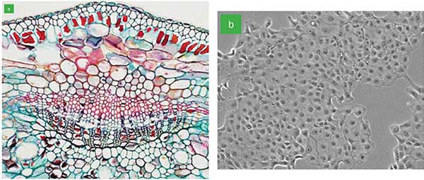
Figures 1a, 1b. Bright-field microscope images depicting stained slides (a) and a phase contrast image of cells in a migration chamber (b). Courtesy of Robert Hartley.
LED illumination has become an option in bright-field microscopy, but it is in the field of fluorescence microscopy that it has made the largest impact. Until the last decade, the high-pressure mercury-vapor arc-discharge lamp was standard with xenon as an alternative for quantitative work; it was about this time that LEDs emerged as an option in fluorescence microscopy. LEDs overcame many of the problems associated with arc lamps, including the repeated exchange of bulbs and subsequent alignment, restart times, fluctuations in intensity after start-up, and intensity drop-off over time.
The ability to overcome the failings of mercury and xenon systems was not initially achieved by LED manufacturers. For researchers requiring a single- or a two-color system, LEDs were immediately suitable. However, what the main-stream market required was a light source suitable for the standard range of fluorophores (DAPI, FITC, TRITC, Cy5), as well as the flexibility to use Cy5.5, Cy7, CFP, YFP, etc. The higher-end LED systems with four “fixed” channels, did find their place, but did not make the desired impact.
The role of the general light source was filled by metal-halide light sources. Halide bulbs lasted for 2,000 hours and, importantly, they offered more flexibility than four-channel LED units. Halide sources do have some disadvantages, too. The bulbs are lit for the duration of time that the microscope is on, whereas LEDs are only on for the brief period of acquisition. The fluctuation coefficient of some halide light sources can be as much as 10 percent.
Halide light sources by nature project UV and IR to the light guide. Light guides in halide systems need to be replaced after a period of time due to degradation by UV and IR. But LEDs are less harmful for the light guide, eliminating any degradation.
To make an impact, LED manufacturers required a system that could deliver illumination across the spectrum, from 365 to 700 nm and longer. Production of an effective white light source by combining multiple wavelengths offered a direct replacement onto a user’s existing microscope system and filter cubes. These also provided the additional advantage of 0 to 100 percent intensity adjustment, stable intensity over time (Figures 2a and 2b), instant on/off and the opportunity to be integrated into software.
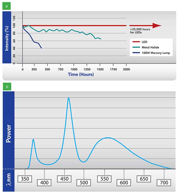
Figures 2a, 2b. The intensity of LED-based light sources have a better lifetime and intensity stability than mercury or halide light sources (a). The spectral range covers the peak excitation of the majority of fluorophores used in most techniques (b). Courtesy of CoolLED.
White light LED illumination systems should be considered a cost-effective replacement for metal-halide and mercury.
As mentioned above, the major manufacturers initially built four-color LED sources for more advanced routines, including multicolor, time-lapse imaging. These offered many advantages such as intensity-stability and speed over the more traditional light sources.
In a standard time-lapse microscope system with an internal shutter, the shutter would be opened, the camera exposure is engaged and then the shutter is closed for each picture. This can still leave the sample exposed to light from an arc lamp for up to double the camera acquisition time and may lead to phototoxicity and experiment failure.
In an experiment, it is always advisable to take images from multiple sites in a sample. This ensures that the images are representative of the sample as a whole. In some scenarios it is difficult to visit the number of points required for statistical significance within the cycle time in the experimental protocol. Even in a simple situation, where the researcher has a motorized microscope and automatically changes filters in a carousel, the switching time between colors can range from 500 to 800 ms, with a slow shutter time of 200 ms. To overcome this deficiency, some microscope manufacturers employ advanced arc illumination systems with fast internal shutters (1 ms), as well as fast filter wheels and attenuator with 50-ms delay between adjacent positions. However, activating these components consecutively still adds time overhead and leads to slower image capture. For faster imaging, some companies have employed real-time controllers to change components in parallel; the added complexity and cost of such systems puts them out of the range of a standard research lab. The original four-channel LED units gained some success in these situations, as there was no need to employ a hardware shutter, attenuator wheel, or filter wheel to a microscope equipped with a multiband dichroic. The individual LEDs could be switched on by TTL trigger in <1 ms with the required intensity, offering significant speed improvements.
For example, when three colors are imaged with a camera exposure time of 50 ms in an arc-lamp-equipped motorized microscope, the time at each position is 2 to 3 seconds, depending on the speed of the components. For an LED and the microscope equipped with a multiband dichroic, the cycle time is 151 ms. While a high-speed system is faster, LEDs can outperform them significantly. The main barrier to uptake has been the relative inflexibility of the four-line systems. Now, the latest generation of LED systems has overcome these concerns, as they are equipped with up to 16 wavelengths (Figure 3), spanning 365 nm to 770 nm with the ability to trigger combinations of LEDs suitable for the major quad-band filter cubes on the market.
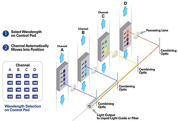
Figure 3. Wavelengths can be chosen and combined to accommodate the combinations of quad bandpass filter cubes commonly available to microscope systems. Courtesy of CoolLED.
They have now become the illumination system of choice for general high speed, time-lapse imaging and also some advanced techniques mentioned below.
Focus drift correction
LEDs are not just used for illuminating a sample in time-lapse microscopy. They are also used in most focus drift correction systems (from manufacturers such as Leica, Nikon and Zeiss), which are feedback devices used to maintain focus.
At high magnifications, the in-focus plane is a few microns, making such small focal planes susceptible to focal drift, which is typically caused by thermal expansion and contraction.
To overcome the challenge of thermal drift, there are two common approaches: software-based algorithms and hardware-based z-correction. Software routines can adequately maintain focus as long as cells are restricted to a similar image plane, but can be confused by free floating non-adherent cells. In hardware drift correction systems, light is back-reflected down the objective to a detector, monitored in real time and relayed into the microscope Z-drive. This will maintain the desired focal position irrespective of the cellular environment and is crucial for many research projects such as focal adhesion formation or new superresolution techniques (i.e. PALM, STORM and GSD).
Advanced techniques using LED illumination
There is a whole range of newly emerging techniques that have traditionally employed laser light to illuminate a sample, but are now turning to LEDs. An example is structured illumination microscopy (SIM), a wide-field technique that can improve the lateral resolution beyond the diffraction limit by a factor of two. This is achieved by projecting a series of patterns sequentially onto a sample and capturing images, followed by post-processing. Fast LED color switching and deformable mirror devices (DMD) for generating the pattern means high speeds can be achieved compared to the traditional mechanical method of structured pattern generation.
Until recently, spinning disc confocal microscopy systems featured laser illumination due to light loss through the system. However, now that LEDs are more powerful, they are being used in some of the less expensive systems. With discs that permit greater transmission of light, LEDs have been especially successful. Other methods where LEDs have become a cheaper alternative are in TIRF microscopy, photodynamic therapy (where light is used to reduce tumors), Forster resonance energy transfer (FRET) for determining protein-protein interaction and in calcium imaging. LED use in calcium imaging has become widespread because of its sub-millisecond switching and higher stability, as compared to the fastest short-arc grating-based systems. Previously, ratiometric images could be imaged at 10 fps. The speed has increased to 100 fps with LEDs.
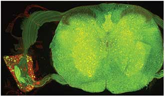
Figure 4. Cross section of the mammalian spinal cord and dorsal root ganglion. All neurons are labeled in red with a subset expressing eGFP. Courtesy of Robert Hartley.
Optogenetics
In neuroscience, there is a long-standing desire to selectively target one cell type for investigation without affecting other cells in the sample (Figure 4). This was achieved, in part, 15 years ago by using Cre-Lox methods of labeling cells that transiently express genes known to be selective for that cell type (Figure 5). However, even though the cell types could be labeled, the method of recording from the individual cells was technically challenging or potentially damaging to the tissue and therefore not always suitable.
Some of these challenges were overcome with the development of optogenetics in 2005. Optogenetics marries optical modulation of action potentials with genetic methods of selectively targeting single cell types in a heterogeneous population, such as in brain tissue. It is based on modifications of bacterial opsin, a single unit, light-activated ion pump that is selectively delivered into target cells via viral vectors. Shining focused light onto the cells will selectively activate or inhibit, depending on the ion channel expressed.
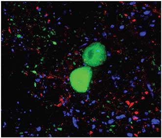
Figure 5. Section of the mammalian spinal cord taken at high magnification (63×), showing individually labeled cells (large, green) and their local synapses (small, green puncta). Red and blue puncta represent inhibitory and excitatory synapses in the region. Courtesy of Robert Hartley.
Until the past several years, lasers were still considered the preferred choice for optical stimulation due to their narrow spectral line width and lower dispersion in tissue than noncoherent sources. However, the narrow full width half maximum (FWHM) of LEDs, the recent increase in power/light delivery (100 mW/mm2 at the end of a fiber, approximately 1 percent of total LED power) and fast temporal switching of LEDs make them now the preferred choice. “As far as optogenetics applications are concerned, LEDs surpass lasers in almost every respect,” according to OpenOptogenetics (http://openoptogenetics.org/). As the protocols for optogenetics become more standardized, and within the capability of new research labs, LED light sources are increasingly the more attractive choice for research groups.
LEDs always had their place where one or two wavelengths were required, where flexibility beyond four colors was not necessary, or where speed was a crucial factor. However, with the recent introduction of full spectrum light units and more advanced systems with up to 16 wavelengths and rapid triggering, LED illumination has become the new standard in fluorescence microscopy. LEDs have even started to make inroads into domains that were once the sole preserve of high-power arc lamps and lasers — for example, spinning disc confocal systems and structured illumination superresolution microscopy.
With each incremental power increase, the scope of research that will rely on LEDs will only increase. The future is bright indeed.
Meet the author
Dr. Robert Hartley is field sales manager at CoolLED Ltd. in Andover, England; email:
[email protected].