Full company details
Instrument Systems GmbH
Member of the Konica Minolta Group
 Kastenbauerstr. 2
81677 Munich
Germany
Phone: +49 89 454943 0
Fax: +49 89 454943 11
Growth in OLED Lighting Demands New Metrological Traceability
Photonics Spectra
Feb 2021The rapidly emerging dominance of OLED technology for illumination and display applications is driving demand for a metrology tailored to these light sources.TOBIAS SCHNEIDER, INSTRUMENT SYSTEMS OPTISCHE MESSTECHNIK GMBH
The increasingly broad transition from incandescent light bulbs to OLEDs for general lighting poses new challenges to light measurement. OLEDs exhibit completely different and far greater variations in their spectral distribution. This variability does not support optimal measurements using established calibrations with standard illuminant A, due to different spectral sensitivities to errors in calibration and measurement.
Metrological traceability and good control over measurement uncertainties is the key to ensuring reliable, safe, efficient, consistent, and predictable performance of lighting products. Therefore, the ability to adapt metrological procedures and calibration concepts to OLED light sources is essential for our ability to shape the success of OLED technology.
The task of photometry requires a quantitative measurement of the perception of electromagnetic radiation in the wavelength range from 360 to 830 nm via the human eye by determining photometric measurands X
ν:
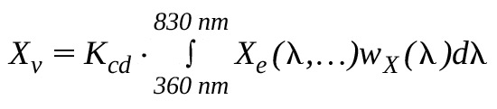
Where X
e(λ) is the spectral density of a basic radiometric quantity X
e (e.g., wattage or irradiance in W/m
2).
The weighting function wX(λ) describes the wavelength-dependent absorption by the eye.
The most important weighting functions are the three so-called color matching functions
x,
y ,
z . They are modeled after the absorption curves of the three cell types in the eye that are responsible for color perception in a standard observer set forth by convention
1. The function corresponds to the V(λ) curve for the brightness sensitivity of the eye in good lighting conditions
2. The photometric values
x,
y ,
z resulting from the equation above are the tristimulus values X, Y, Z
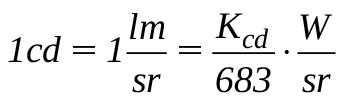
3. The constant K
cd = 638 lm/W defines the photometric unit.
As for any other measurement, a complete reading for the measurands X
ν consists of three components: the numeric value, unit, and measurement uncertainty. The unit and corresponding numerical reading result from the calibration that
assigns an estimate of the value of the measurand to the output of the measurement system — such as a photocurrent or the ADU (analog to digital unit) counts of a CCD detector — via the comparison with a suitable reference. The measurement uncertainty makes a quantitative statement about the reliability of the reading as an estimate of the actual value of the measurand.
Metrological traceability
Traceable readings are normally stated in SI base units, which are standard units of measurement defined by the International System of Units (SI)
4. Since its revision in 2019, the SI system defines seven base units on the basis of seven fundamental physical constants whose values reflect either fundamental physical relationships, such as the speed of light c, or were laid down by convention.
All photometric units in the SI system are defined by the photometric radiation equivalent K
cd = 638 lm/W. The corresponding base unit in the SI system is the unit for luminous intensity, the candela:
SI units are disseminated by calibrations based on a chain of measurements. If this chain can be unequivocally traced to a primary representation of the SI units, it is referred to as the metrological traceability of a measurement.
The measurement uncertainties that occur in every measurement are crucial for metrological traceability. They form links in the “chain” that establishes a demonstrable link to the primary representations of the SI units, and they constitute a quantitative description of the uncertainty of a measurement at each point of the chain (Figure 1).
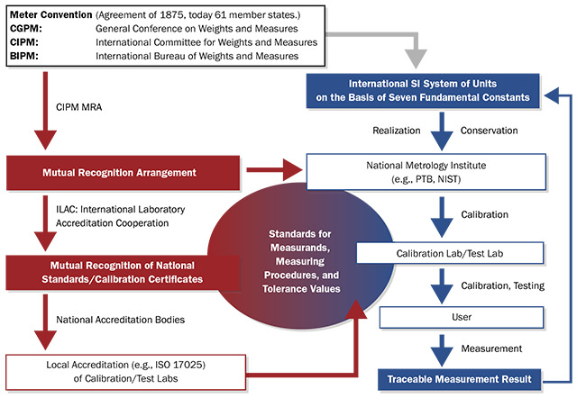
Figure 1. A schematic diagram of the practical application of the metrological traceability of light measurement readings in the International System of Units (SI). Courtesy of Instrument Systems Optische Messtechnik GmbH.
National metrological institutes provide primary realizations of the units. Comparative measurements ensure that the various primary realizations are sufficiently similar to form a uniform system of units. Starting with the primary realizations, the units are distributed over various calibration chains. International standards ensure that this process is reliable and uniform, and they allow users to check the traceability of their readings. The ISO/IEC 17025 “General Requirements for the Competence of Test and Calibration Laboratories” is the most common of these standards — and sometimes a certificate issued to ISO/IEC 17025
5 is the only accepted proof of metrological traceability for a measurement made by a test laboratory.
Calibration process
Two basic methods exist for the calibration of measuring instruments and sources in light measurement. Direct calibration methods either calibrate a detector to a reference source or calibrate a source to a reference detector. Alternatively, indirect calibration by the substitution method calibrates a detector to another detector by comparing measurement signals from the same light source — the transfer standard. The substitution method can apply the same principle to the calibration of light sources. The transfer standard in this case would be a suitable detector.
In both methods, the principle of similarity applies: The more similarity there is between a calibration object and reference or between a reference and test object, the smaller the measurement uncertainties of the measurement result.
Until recently, incandescent light bulbs have been used almost exclusively as reference sources for the dissemination of units and the calibration of detector systems. So, in most applications, the spectral distribution of reference lamps approximated that of standard illuminant A
6, representing a Planckian radiator with a temperature of 2856 K. Following the principle of similarity, the strong normative reference of photometry to standard illuminant A was an advantage when incandescent light bulbs were a predominant lighting source, and measuring instruments could be easily compared based on their readings of a realization of standard illuminant A. This enabled their characterization and classification by only a few quality indices
7,8.
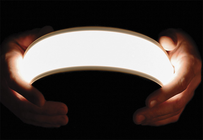
Flexible lighting OLED panels. Courtesy of Instrument Systems Optische Messtechnik GmbH.
The emergence of OLEDs as the dominant source for general lighting and display applications has posed new challenges to light measurement technology (Figure 2). In addition to exhibiting fundamentally different spectral distributions, OLEDs also demonstrate much more variation in those distributions compared to incandescent bulbs. Consequently, the accuracy of a given photometer can no longer be determined by its measurement of a single representative standard light source, and particularly not with standard illuminant A.
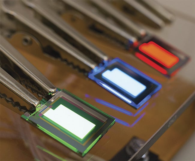
Figure 2. OLED displays are tested on a probe station. Courtesy of Instrument Systems Optische Messtechnik GmbH.
Challenges of the OLED age
Despite years of improvements in measurement technology, the measurement of OLEDs poses new challenges all along traceability chains based on Standard
Illuminant A, including the following:
- End users are often confronted with larger or even unknown measurement uncertainties when measuring OLEDs with equipment calibrated by incandescent reference sources. Further, the selection of instruments based on existing classification systems and quality indices will no longer necessarily deliver the best possible result.
- Manufacturers of light measurement equipment and test laboratories must balance conformity with calibration standards and classification systems against optimal performance in customer applications.
- Standardization bodies, such as the International Commission on Illumination (Commission Internationale de l’Éclairage, or CIE), face the challenge of extending and adapting their photometric standards to a rapidly evolving technology9-11.
Imaging colorimeter
The previously discussed concepts and challenges of photometry in the age of OLED technology can be illustrated using the example of an imaging colorimeter (Figure 3). In contrast to spectroradiometers, a colorimeter does not measure the full spectral distribution of light at its input to calculate photometric quantities of interest (see first equation). Instead, it estimates values for the quantities of interest from a small discrete set of transmission measurements taken through a set of optical filters.
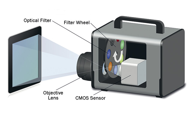
Figure 3. The measuring principle of a filter-based imaging colorimeter for the measurement of CIE (Commission Internationale de l’Éclairage) tristimuli X, Y, Z. Courtesy of Instrument Systems Optische Messtechnik GmbH.
In its basic version, an imaging colorimeter, such as the LumiCam 2400B from Instrument Systems, sequentially takes images of a light source in three or more filter channels with relative spectral transmissions aligned to produce a relative spectral sensitivity close to the CIE color matching functions
x,
y ,
z — taking into account the relative spectral transmission/sensitivity of the imaging optics as well as the CMOS sensor (Figure 4).
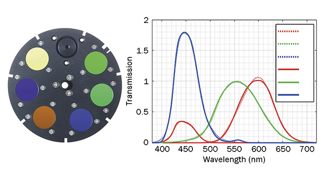
Figure 4. For the filter channels, the relative spectral transmission of all system components is taken into
account, so that the overall relative spectral sensitivity is close to the CIE color matching functions x, y , z . Courtesy of Instrument Systems Optische Messtechnik GmbH.
Spectral integration of the CMOS sensor and suitable calibration of the overall spectral sensitivity allows the camera to make spatially resolved measurements of the tristimuli X, Y, Z from which other colorimetric quantities can then be calculated. Since the camera is mainly used for the measurement of displays, it is configured with a calibration to luminance in units cd/m
2. Technically, a more precise adjustment of detector sensitivity can be achieved by dividing the measurement of X into two separate filter channels. But this comes at the expense of an additional measurement. Measurements with the -
adjusted filter determine the photometric integral Y so that the camera can be used as an imaging photometer with a single measurement.
Calibration of all filter channels to a realization of illuminant A ensures compliance with established standards and classification systems. The metrological traceability of the readings and the measurement accuracy are confirmed by a test certificate accredited to ISO 17025.
Multiple calibrations
The standard calibration does not generally yield optimal results in the measurement of OLEDs. Adjustments to calibration processes by the manufacturer (Figure 4) can yield substantial improvements, such as instruments offering
several user-selectable calibrations preoptimized by the principle of similarity for various measurement applications. However, this is only practical in special cases because the potential applications are not always known at the time of calibration, and suitable reference sources are not
always available.
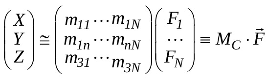
Further optimization possibilities exist by making better use of the calibration matrix of the system that establishes the relationship between the measurement signals — such as the signals of the N = 4 filter measurements — and the tristimuli X, Y, Z:
For standard calibration, only components m
11, m
12 for the
x filter values F
X1, F
X2; m
23 for the
y filter value F
Y; and m
34 for the
z filter value F
Z of the calibration matrix M
C are different from zero. With a perfect filter match, this calibration would be optimal for measurement of any spectral distribution. However, in reality each filter adjustment has only a finite accuracy. So, errors will occur in the measurement of light sources with a spectral distribution deviating from that of the calibration reference.
If the spectral characteristics of the filter mismatch are known, a matrix M
C can be defined by numerical optimization that ensures the lowest measurement uncertainties for a given set of spectral distributions and the selected measure of optimization, which is typically determined by minimizing the average measurement error. In this way, measurement errors can be reduced for both generic and application-specific spectral distributions. Further improvements depend on understanding the filter mismatch, the number of parameters of the calibration matrix, and the selected spectral distributions.
This example demonstrates how accurate metrological traceability amidst the emerging OLED age can be mastered by supplementing proven principles of light measurement technology with adapted calibration concepts and modern instrument technology and data processing. In this way,
it is possible to satisfy the requirements for measurement accuracy, as well as those of an international body of standards, which are lagging behind the development of the technology itself.
Meet the author
Tobias Schneider, Ph.D., is a scientist in the Metrology Group at Instrument Systems Optische Messtechnik GmbH. He earned his doctorate at the Physikalisch-Technische Bundesanstalt and is an active member of the International Commission on Illumination (CIE) and the Illuminating Engineering
Society (IES); email:
[email protected].
References
1. ISO 11664-1:2019 Colorimetry — Part 1: CIE Standard Colorimetric Observers,
http://eilv.cie.co.at/term/163.
2. CIE 018:2019, The Basis of Physical
Photometry, 3rd ed.
3. ISO 11664-3:2019 Colorimetry — Part 3: Tristimulus values.
4. BIPM (2019). The International System
of Units, 9th ed., www.bipm.org/utils/
common/pdf/si-brochure/SI-Brochure-
9.pdf.
5. DIN EN ISO/IEC 17025:2017, General requirements for the competency of test
and calibration laboratories.
6. ISO 11664-1:2020 Colorimetry — Part 2: Standard Illuminants, http://eilv.cie.co.at/term/168.
7. CIE S023:2013, Characterization of the Performance of Illuminance Meters and Luminance Meters.
8. CIE 231:2019, CIE Classification System
of Illuminance and Luminance Meters.
9. CIE 015:2018, Colorimetry, 4th ed.
10. CIE S025:2015, Test Method for LED Lamps, LED Luminaires and LED Modules.
11. CIE TC2-90, LED Reference Spectrum for Photometer Calibration, http://cie.co.at/technicalcommittees/led-reference-spectrumphotometer-calibration.